Angle grinder

Inactive Publication Date: 2003-12-30
ROBERT BOSCH GMBH
View PDF8 Cites 8 Cited by
  • Summary
  • Abstract
  • Description
  • Claims
  • Application Information

AI Technical Summary

Benefits of technology

The angle grinder of the invention as defined by the characteristics of claim 1 has the advantage over the prior art that the entire housing can be made by shell construction and can be fabricated from an economical material; only the insert part to be inserted separately into the housing has to comprise especially high-quality material. The possibility is thus afforded of producing a less expensive product than was previously possible. This is made possible by the fact that the entire housing is made of shell construction, that is, with a mounting shell and a cap shell, between which the insert part is inserted. Because the insert part is fixed with its first and second fixation device between the mounting shell and the cap shell, the spindle bearing receptacle and the spindle locking receptacle, also disposed in the insert part, always remain stationary in their position relative to the housing.

Problems solved by technology

Since the spindle bearing receptacle is embodied integrally with the housing, the entire housing must be made from such a high-quality, expensive material.

Method used


Image

  • Angle grinder
  • Angle grinder
  • Angle grinder

Examples


Embodiment Construction

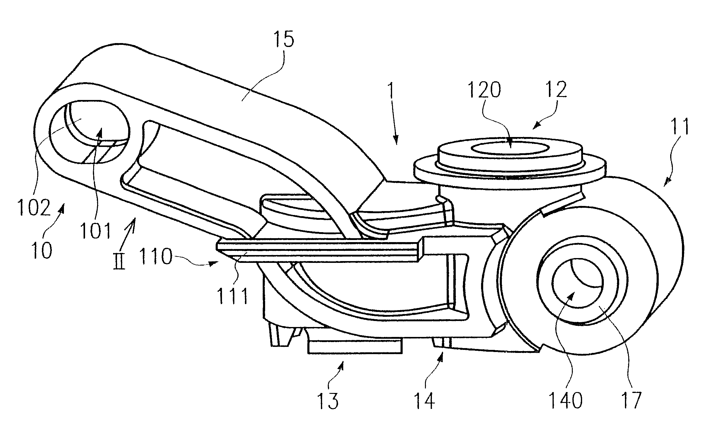
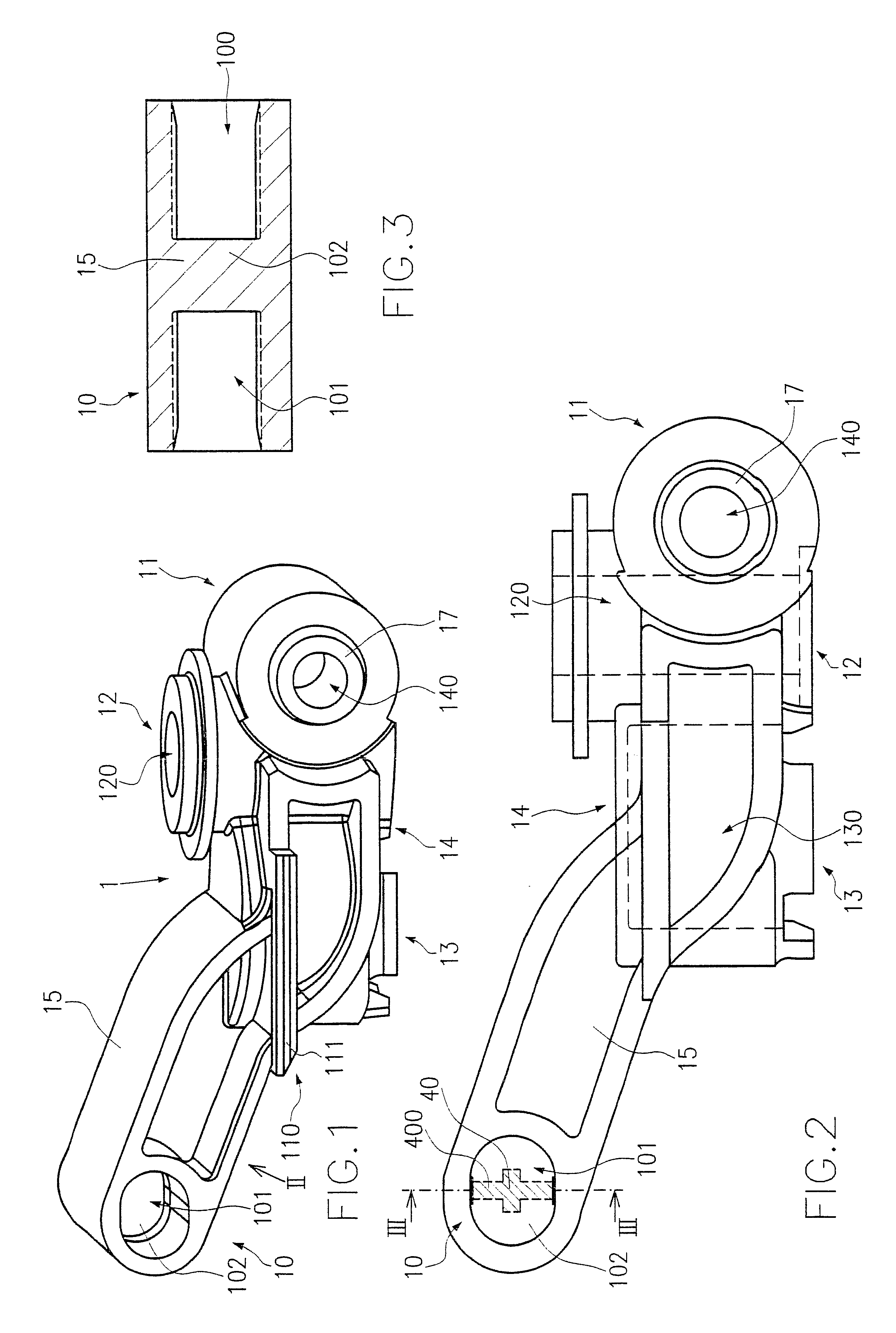
FIGS. 1 and 2 show views of an insert part 1. Identical parts are identified by the same reference numerals. The insert part 1 has a base body 14 and an outrigger 15. A spindle bearing receptacle 13, spindle locking receptacle 12, and second fixation device 11 are embodied on the base body 14. The spindle bearing receptacle 13 is embodied as a blind bore 130 (shown in dashed lines in FIG. 2). The spindle locking receptacle 12 is designed as a through hole 120 (shown in dashed lines in FIG. 2). The longitudinal center axes of the through hole 120 and the blind bore 130 are oriented parallel. The second fixation device 11 has an aperture 140, which is oriented perpendicular to the plane defined by the two longitudinal center axes of the through hole 120 and the blind bore 130. A first centering device 16 (see FIG. 6) and a second centering device 17 are embodied in the region around each of the two openings of the through hole 120.

Fins 110, 111 are provided laterally on the base body ...


PUM


Abstract

An angle grinder with a housing 2 can be produced more economically by providing that it has a mounting shell 3, a cap shell 4, and an insert part 1 between these two shells. The insert part 1 is equipped with a first fixation device 10 and a second fixation device 11 for fixation between the mounting shell 3 and the cap shell 4, and it has a spindle locking receptacle 12 and spindle bearing receptacle 13. The mounting shell 3 has a first fixation means 30, which is engaged by the first fixation device 10 of the insert part 1. The cap shell 4 has a second fixation means 40, which engages the fixation device 10 of the insert part 1. The insert part 1 also has a second fixation device 11, which can be brought into engagement with suitable means on the mounting shell 3 and the cap shell 4.

Description

PRIOR ARTThe invention is based on an angle grinder as generically defined by the preamble to claim 1.An angle grinder with such a housing is known from German Patent Disclosure DE 43 44 128. The housing in this case is in one piece and is screwed onto a cup-shaped motor housing. A spindle bearing receptacle in which the bearing for a work spindle is received is embodied integrally with the housing. For changing a tool that is mounted on the work spindle, the work spindle has to be fixed. This is done by providing that a spindle lock, by means of a hand lever and counter to the force of a restoring spring, presses a detent cam into an indentation that is embodied on a clamping flange, which in turn is connected to the work spindle in such a way that it rotates with it. In the operation of the work spindle and when the tool secured to it is changed, major forces, or clamping forces, occur. It is therefore necessary that both the spindle bearing receptacle and the locking device compr...

Claims


Application Information

Patent Timeline
IPC IPC(8): B24B23/02B24B23/00B25F5/00B25F5/02
CPCB25F5/02B24B23/028
Inventor WALZ, ROLANDSTIERLE, PETERDAMMERZ, RALPHSULEA, MARIA-MARGARETTAHEESS, STEFAN
Owner ROBERT BOSCH GMBH
Why Eureka
Try Eureka