Electrographic Printing Apparatus, Electrographic Printing Method, and Method of Producing Glass Plate

a printing apparatus and electrographic printing technology, applied in the direction of electrographic process apparatus, instruments, optics, etc., can solve the problems difficult to completely avoid the generation of base fogging at all, and the performance of the device is reduced, so as to achieve the effect of reducing the voltage tolerance, preventing base fogging, and small performance drop

Inactive Publication Date: 2009-07-02
MITSUBISHI HEAVY IND LTD
View PDF6 Cites 3 Cited by
  • Summary
  • Abstract
  • Description
  • Claims
  • Application Information

AI Technical Summary

Benefits of technology

[0050]In this way, since a glass plate with an image that does not have base fogging can be obtained, a high-quality product with a smaller decrease in performance, such as the generation of electric noise and a decrease in the voltage tolerance, is obtained, particularly when an electric circuit is formed by a conductive pattern.
[0051]According to the present invention, since the toner in the non-image region is removed, base fogging can be prevented, and high printing quality without a decrease in performance, such as the generation of electric noise and a decrease in the voltage tolerance, can be achieved.
[0052]By applying a predetermined voltage to the developer removing drum, the toner is attracted toward the carrier by the potential difference in the non-image region, and the toner strongly adheres to the supporting body in the image region. In this way, high quality printing can be achieved.

Problems solved by technology

However, when forming a conductive pattern for an industrial product, base fogging is not acceptable even when it is not visibly noticeable because it is likely to cause a decrease in performance, such as the generation of electric noise and a decrease in the voltage tolerance.
However, there is a problem in that it is difficult to completely avoid the generation of base fogging at all with the current two-component development method based on the above-described principle.
However, with these methods, too, base fogging occurs because toner is supplied to and contacts the non-image regions on the photoreceptor.

Method used


Image

  • Electrographic Printing Apparatus, Electrographic Printing Method, and Method of Producing Glass Plate
  • Electrographic Printing Apparatus, Electrographic Printing Method, and Method of Producing Glass Plate
  • Electrographic Printing Apparatus, Electrographic Printing Method, and Method of Producing Glass Plate

Examples


first embodiment

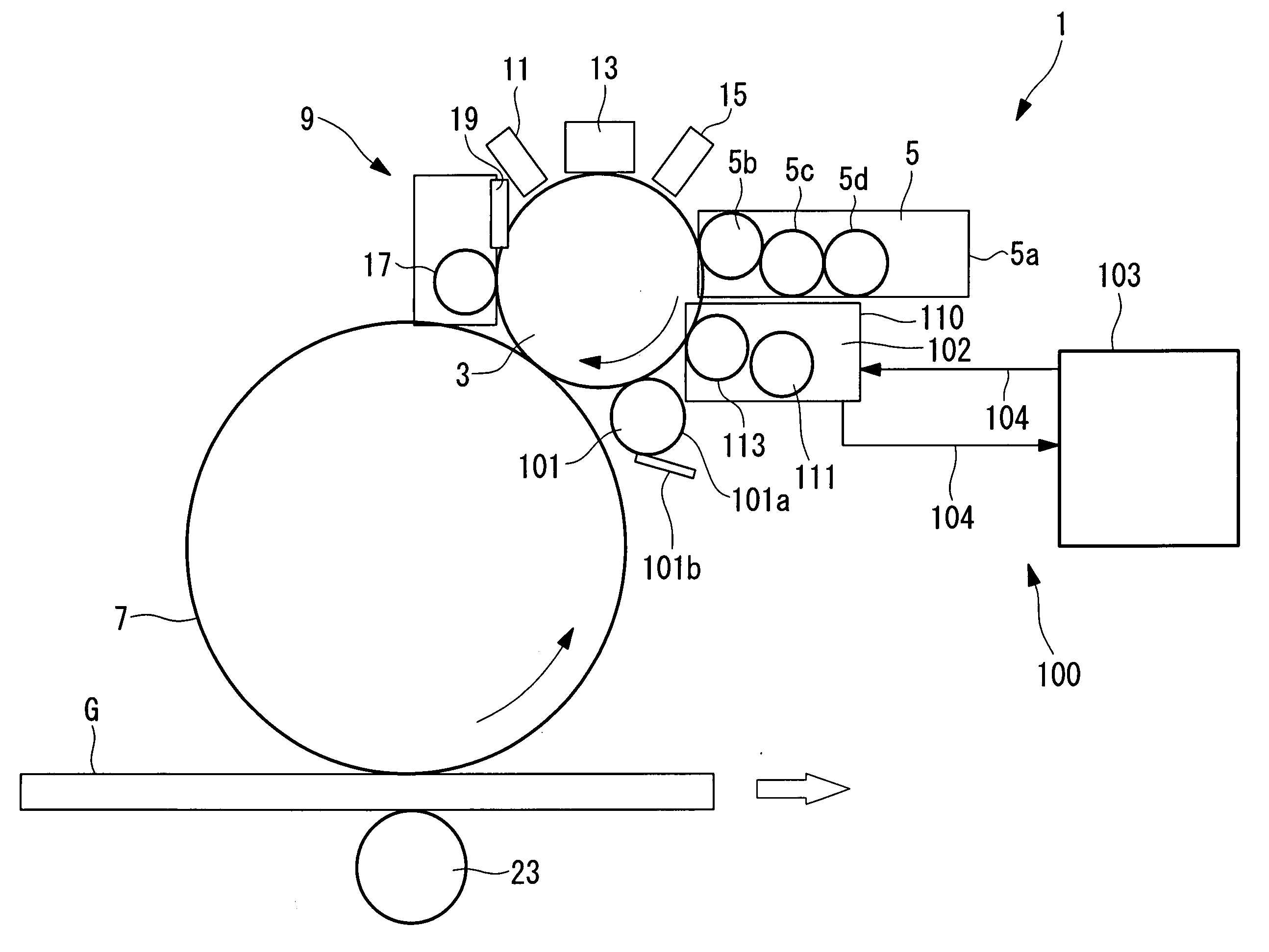
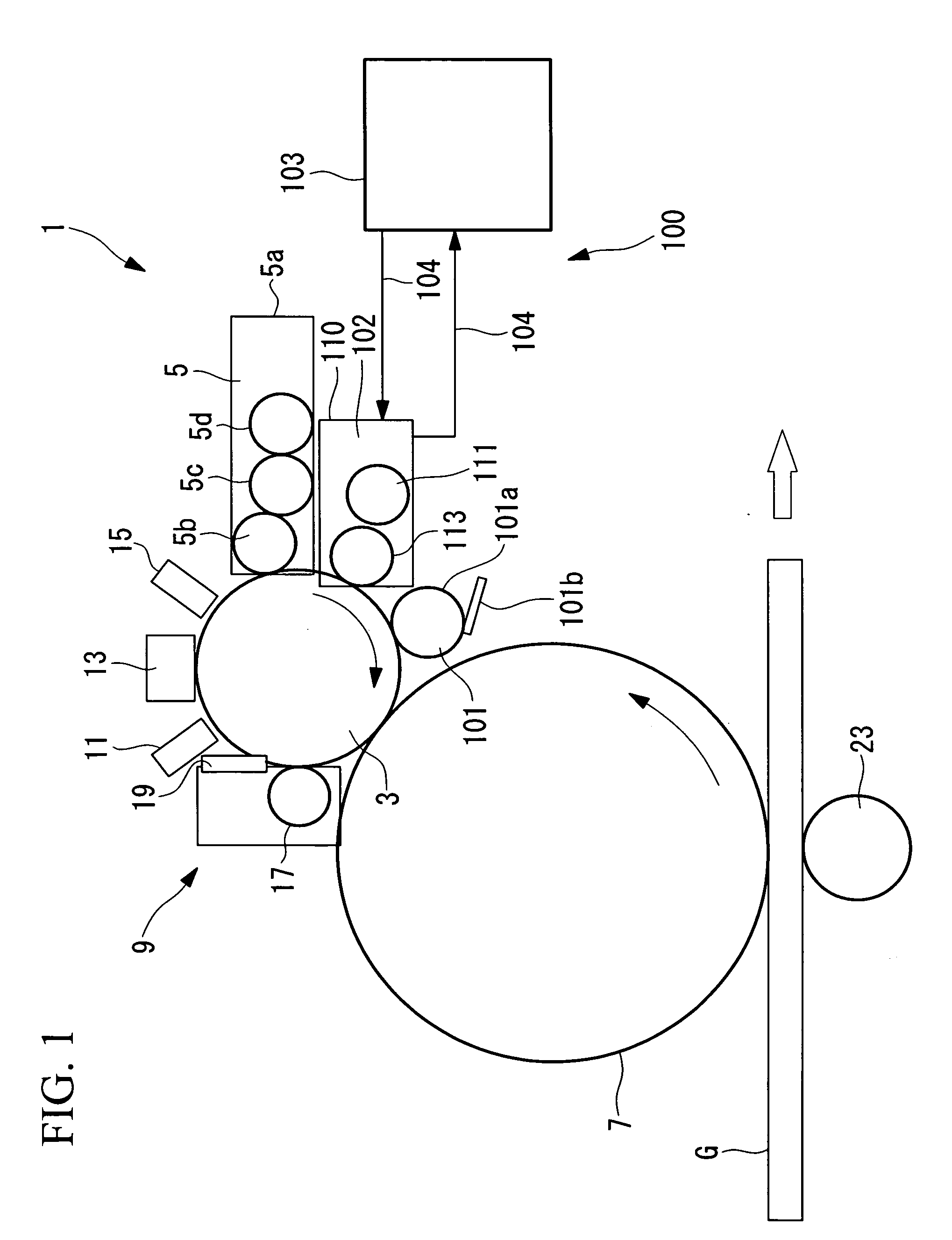
[0073]An electrographic printing apparatus according to a first embodiment of the present invention will be described below with reference to FIGS. 1 to 9.

[0074]FIG. 1 illustrates, in outline, the electrographic printing apparatus according to this embodiment.

[0075]As shown in FIG. 1, an electrographic printing apparatus 1 is mainly formed of an organic photoconducting (OPC) photoreceptor (photoreceptor) 3 that forms an image by selectively attracting a toner; a developing device 5 that supplies the toner, included in a developer containing the toner and a carrier, to the OPC photoreceptor 3; an intermediate body 7 that transfers the toner attracted to the OPC photoreceptor 3 onto a glass plate G; and a non-image-region toner removing device 100.

[0076]The electrographic printing apparatus 1 of this embodiment described below is employed to form a prescribed pattern of metal wires on the glass plate G.

[0077]The toner used in this embodiment is made by finely pulverizing a mixture of ...

second embodiment

[0150]Next, a second embodiment of the present invention will be described with reference to FIGS. 10 to 12.

[0151]The basic configuration of this embodiment is the same as that of the first embodiment, except that the configuration of the non-image-region toner removing device 100 differs. Therefore, in this embodiment, only this difference is described, and descriptions of other parts are not repeated.

[0152]Components that are the same as those in the first embodiment are represented by the same reference numerals, and detailed descriptions thereof are not repeated.

[0153]FIG. 10 illustrates, in outline, an electrographic printing apparatus according to the second embodiment.

[0154]As shown in FIG. 10, a non-image-region toner removing device (non-image-region toner removing unit) 200 includes a magnetic drum (supporting body) 203, a carrier delivering device 204, a magnetic head 205, a carrier cleaner 206, and a demagnetizing head 207.

[0155]The magnetic drum 203 is substantially cyl...


PUM

PropertyMeasurementUnit
particle sizeaaaaaaaaaa
particle diameteraaaaaaaaaa

Abstract

An electrographic printing apparatus and an electrographic printing method that prevent base fogging and maintain high quality are provided. The provided electrographic printing apparatus includes a OPC photoreceptor to which a developing device adheres charged toner to an image region of an electrostatic latent image formed on a moving surface; and a non-image-region toner removing device disposed downstream of the developing device in a moving direction of the surface of the OPC photoreceptor and at a position opposing the OPC photoreceptor, wherein the non-image-region toner removing device includes a removing roller that moves close to the OPC photoreceptor and attracts and delivers a carrier by a magnetic force, and a predetermined electric potential is applied to generate an electric field from a non-image region of the electrostatic latent image to the removing roller.

Description

TECHNICAL FIELD[0001]The present invention relates to an electrographic printing apparatus, an electrographic printing method, and a method of producing a glass plate.BACKGROUND ART[0002]Known electrographic printing apparatuses irradiate a uniformly charged photoreceptor with light from a light source, such as a laser or a light emitting diode (LED), to form an electrostatic latent image on the photoreceptor by neutralizing image regions that are irradiated with light and forms an image by adhering toner, which is charged to the same polarity as the photoreceptor, to the image regions.[0003]A two-component development method is known as a method of adhering toner to a photoreceptor. The two-component development method is a method of transferring a toner (particle size of 6 to 20 μm), which is adhered to the surface of a carrier, onto a photoreceptor by rubbing the surface of the photoreceptor with a magnetic brush formed of the carrier, which consists of magnetic particles (partic...

Claims


Application Information

Patent Timeline
Patent Type & Authority Applications(United States)
IPC IPC(8): G03G21/00
CPCC03C17/008G03G21/0058G03G21/0047G03G15/0815
Inventor OKADA, TOMOAKIKAWANAMI, TOSHIHIKOFUJII, TOMOHIRO
Owner MITSUBISHI HEAVY IND LTD
Why Eureka
Try Eureka