Shock-wave meat treatment

a technology of shock wave and meat, applied in the field of shock wave meat treatment, can solve the problems of high equipment cost, inconvenient use, and inconvenient use, and achieve the effects of reducing the cost of equipment, and improving the quality of mea

Inactive Publication Date: 2003-12-30
HYDRODYNE INC
View PDF36 Cites 17 Cited by
  • Summary
  • Abstract
  • Description
  • Claims
  • Application Information

AI Technical Summary

Benefits of technology

Among the changes, which may be used individually or in combination, are (1) changes in the geometry of the capacitor discharge chamber; (2) the replacement of a tubular chamber for containing the meat with a "drum-head" on which the meat sits and which is located at the upper end of the capacitor discharge chamber; (3) the provision of meat supporting structure which substantially holds the meat in place on the drum-head during capacitor discharge, and at least a portion of which optionally accompanies the meat through several stages of its movement; (4) a simplified indexing carrousel for delivering the meat to a location above the capacitor discharge chamber and for transporting the treated meat to a discharge location; (5) the more effective provision of a rarefaction or negative compression wave; and (6) the provision of certain improvements in tenderization involving subjecting the meat, especially boneless chicken breasts, to shock wave treatment in combination with other operations.

Problems solved by technology

Importantly, this embodiment is inherently a batch operation, and the equipment is expensive.
A stainless steel hemisphere four feet in diameter and two inches thick is not inexpensive, and the equipment needed for moving blast shields, water changers, and so on is complex and costly.
Packing and removing the meat is slow, and further delays are mandated by safety concerns; workers should not load the hemisphere while the explosive is rigged, for example.
Another drawback is that the water is blown upwardly out of the hemispherical shell by the explosion and must be replenished.
This draining and replenishing takes time and uses a great deal of water.
Also, the explosive force in the aforementioned embodiment is not balanced.
The geyser of blast gases, steam, and spray out the top of the hemisphere causes a large reaction force which drives the hemisphere downwardly, and this must be resisted by large springs, dashpots, and so on, this additional equipment also being expensive and tending to deteriorate too quickly.
The placement of the meat against or in near adjacency to the surface of the shock-wave reflective steel is the root of some of the difficulties with previous embodiments as discussed above, and such placement has limitations which prevent any substantial improvement.
However, the problem then arises as to how the meat can be supported against moving away from the explosion.
One is make the container of wires, which sound (and a shock wave) can pass around, but a wire container will not in all cases adequately support the meat; and, depending on the size of the wires or rods from which it is formed, will interfere with the shock wave.
But this would not eliminate all the problems with the earlier embodiments, namely the need for batch processing and the associated slowness and complex equipment.

Method used


Image

  • Shock-wave meat treatment
  • Shock-wave meat treatment
  • Shock-wave meat treatment

Examples


Embodiment Construction

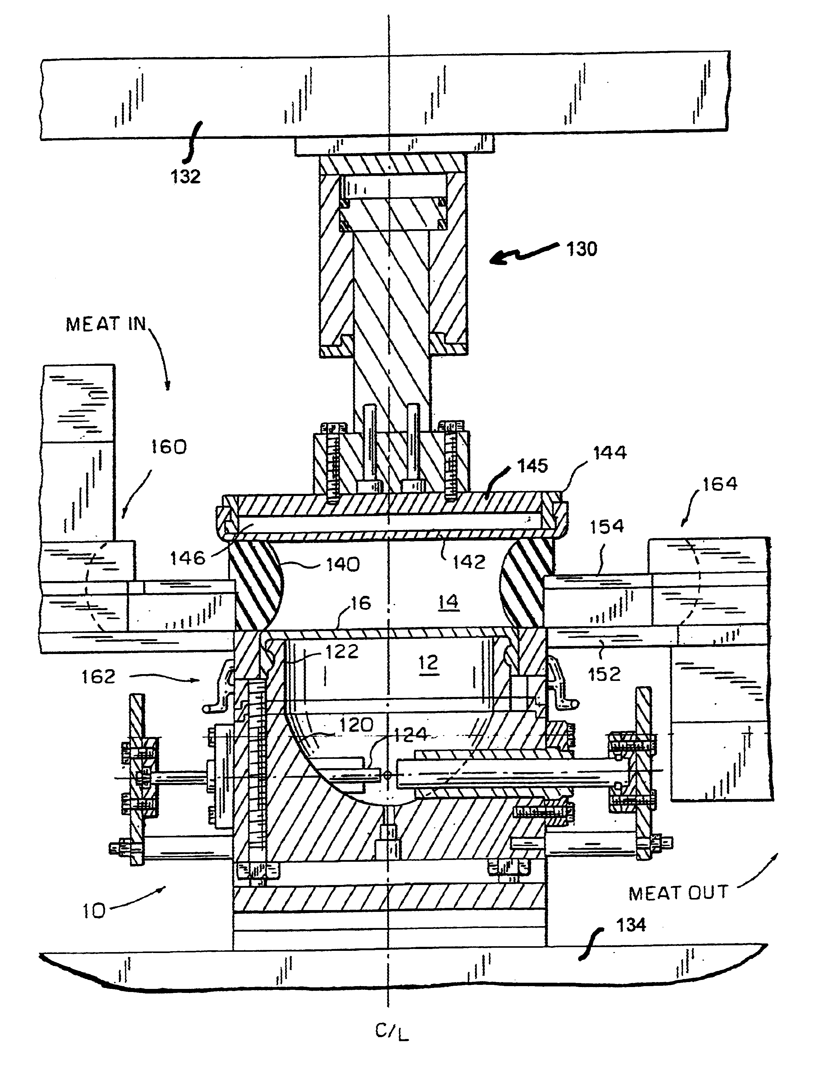
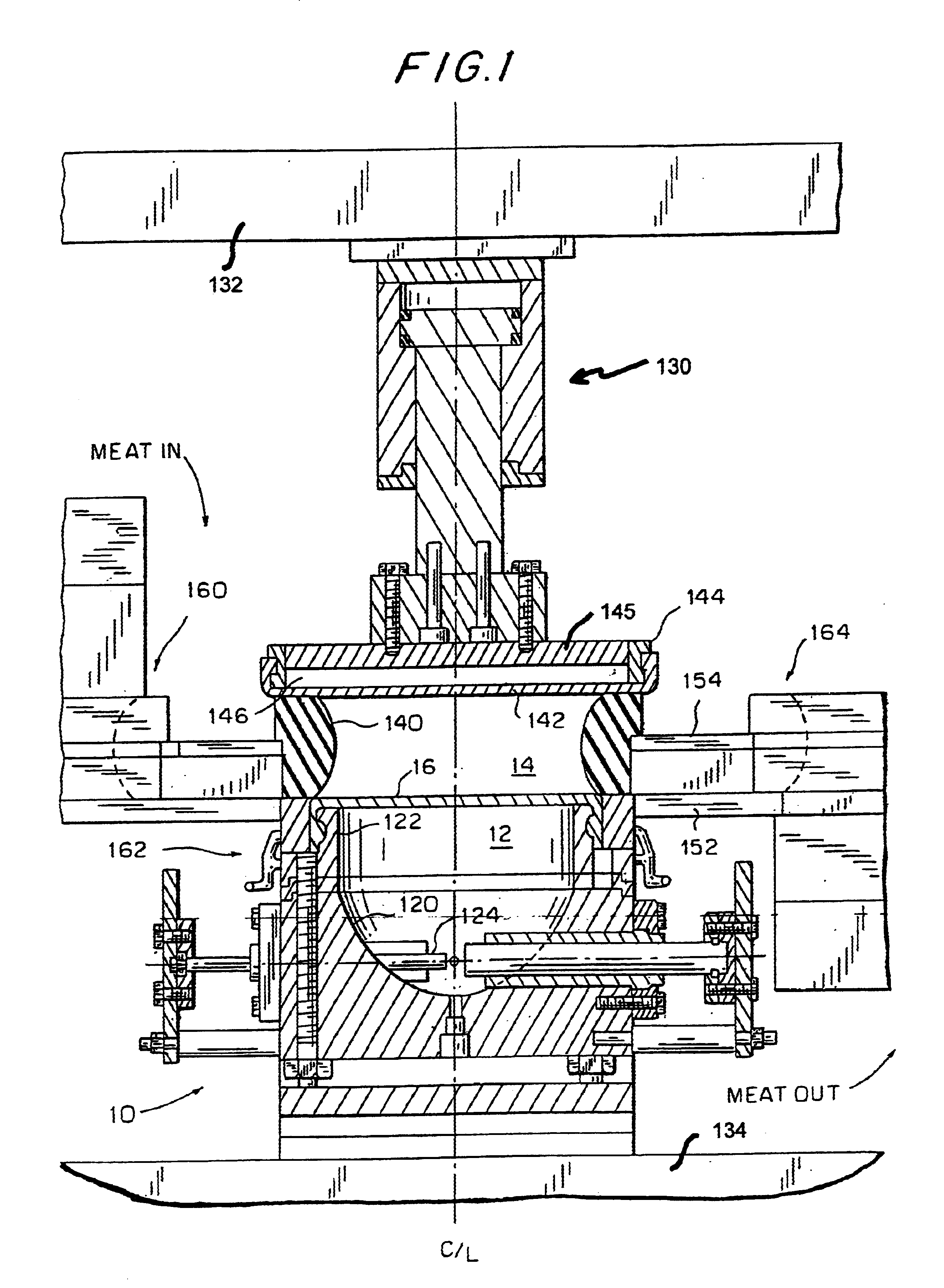
The attached FIG. 1 of a preferred embodiment according to the present invention shows a meat treatment apparatus 10 comprising two main chambers, namely the lower capacitor discharge or firing chamber 12 and immediately thereabove the food processing chamber 14, supported by a lower support structure 134.

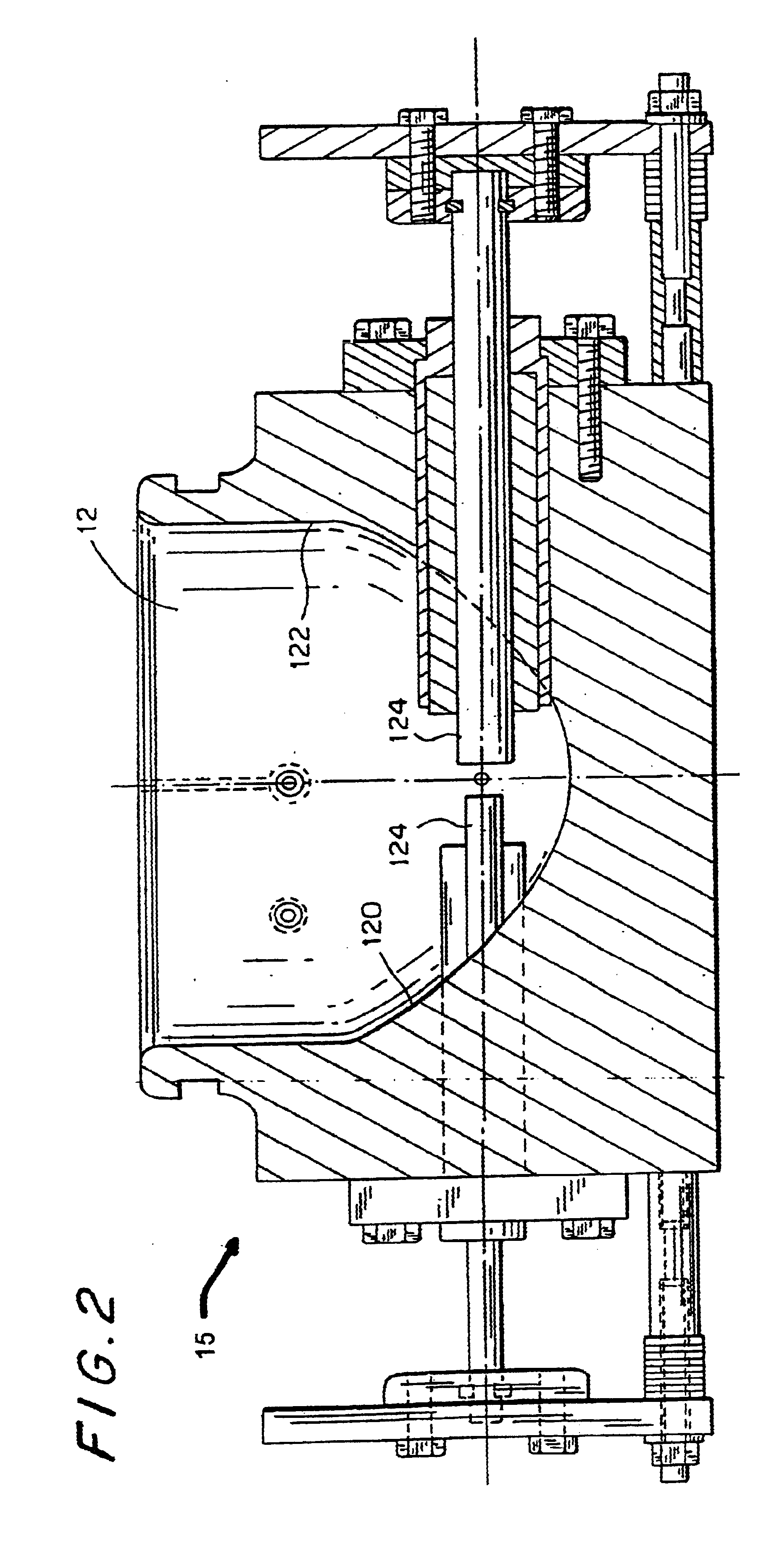
The capacitor discharge chamber 12, filled with water, brine, or another so-called incompressible fluid, consists of a parabolic shaped bowl 120 at the bottom and a substantially circular-cylindrical upper portion 122 which may be slightly cone shaped wherein the angle the side of the cone makes with the center line is less than 15.degree., preferably less than 8.degree. and most preferably 0.degree., i.e. the upper portion 122 is preferably substantially circular-cylindrical, it being understood however that the circular-cylindrical form need not be a perfect circular-cylinder.

Two electrodes 124 enter the parabolic shaped bowl 120 horizontally and are adapted to deliver 12-19 Kj. ...


PUM


Abstract

Improved tenderization of meat is achieved by using, individually or in combination, (1) a capacitor discharge chamber of shortened height; (2) a drum-head on which the meat sits during treatment and which is located at the upper end of the capacitor discharge chamber; (3) meat supporting structure which substantially holds the meat in place on the drum-head during capacitor discharge; (4) an indexing carousel for delivery the meat to a location above the capacitor discharge chamber and for transporting the treated meat to a discharge location; (5) an improved negative compression or rarefaction wave; and (6) the combination of shock wave treatment with other operations.

Description

The present invention relates to the processing of meat for tenderization and / or the killing of bacteria in the meat, by subjecting the meat to shock waves which are plasma waves or pulses generated by capacitive discharge between two electrodes.BACKGROUND AND REVIEW OF RELATED TECHNOLOGYMeat can be tenderized and at least partially sterilized by shock waves, i.e. acoustic or pressure pulses, from explosions caused by a chemical explosive charges or a capacitive discharge between two electrodes, such as shown in the U.S. Pat. Nos. 5,273,766; 5,328,403; 6,120,818 and 6,168,814 B1 in the name of John Long, and U.S. Pat. No. 6,224,476 B1 in the name of Long et al. A shock wave travels outwardly from the explosion site at the speed of sound, or somewhat higher in the case of high-intensity shock waves; and, like an audible sound echoing from a wall, will reflect from a shock-wave reflective surface.The condition for reflection of a shock wave is that the speed of sound, which varies dep...

Claims


Application Information

Patent Timeline
Patent Type & Authority Patents(United States)
IPC IPC(8): A22C9/00A22C21/00A23B4/015A23L5/30A23L13/50A23L13/70
CPCA22C9/00
Inventor LONG, JOHN B.
Owner HYDRODYNE INC
Why Eureka
Try Eureka