
Efficiency thermoelectrics utilizing convective heat flow

a heat flow and thermoelectric technology, applied in the field of improved thermoelectrics, can solve the problems of low system efficiency, low efficiency, and low efficiency of tes, and achieve the effect of outweighing the low efficiency of other qualities of tes

Inactive Publication Date: 2004-01-06
BSST INC +1
View PDF13 Cites 174 Cited by
  • Summary
  • Abstract
  • Description
  • Claims
  • Application Information

AI Technical Summary

Problems solved by technology

However, usages are limited, because system efficiencies are too low to compete with those of most refrigeration systems employing freon-like fluids (such as those used in refrigerators, car HVAC systems, building HVAC systems, home air conditioners and the like).
Several configurations for thermoelectric devices are in current use in applications where benefits from other qualities of TEs outweigh their low efficiency.
None of the existing TE assemblies modify the thermal power transport within the TE assembly by the application of outside influences.

Method used


Image

  • Efficiency thermoelectrics utilizing convective heat flow
  • Efficiency thermoelectrics utilizing convective heat flow
  • Efficiency thermoelectrics utilizing convective heat flow

Examples


Embodiment Construction

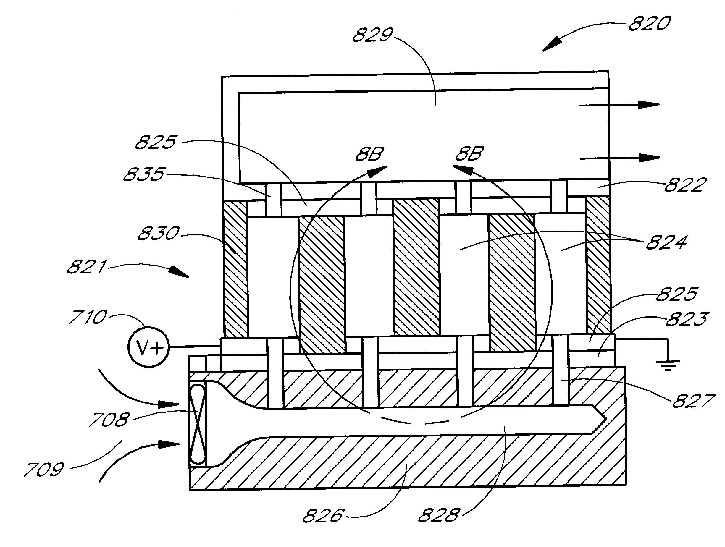
The invention is introduced using examples and particular embodiments for descriptive purposes. A variety of examples are presented to illustrate how various configurations can be employed to achieve the desired improvements. In accordance with the present invention, the particular embodiments are only illustrative and not intended in any way to restrict the inventions presented. In addition, it should be understood that the terms cooling side, heating side, cold side, hot side, cooler side and hotter side and the like do not indicate any particular temperature, but are relative terms. For example, the "hot," "heating" or "hotter" side of a thermoelectric element or array may be at ambient temperature, with the "cold," "cooling" or "cooler" side at a cooler temperature than ambient. Conversely, the "cold," "cooling" or "cooler" side may be at ambient with the "hot," "heating" or "hotter" side at a higher temperature than ambient. Thus, the terms are relative to each other to indicat...


PUM


Abstract

An improved efficiency thermoelectric system is disclosed wherein convection is actively facilitated through a thermoelectric array. Thermoelectrics are commonly used for cooling and heating applications. Thermal power is convected through a thermoelectric array toward at least one side of the thermoelectric array, which leads to increased efficiency. Several different configurations are disclosed to provide convective thermal power transport, using a convective medium. In addition, a control system is disclosed which responds to one or more inputs to make adjustments to the thermoelectric system.

Description

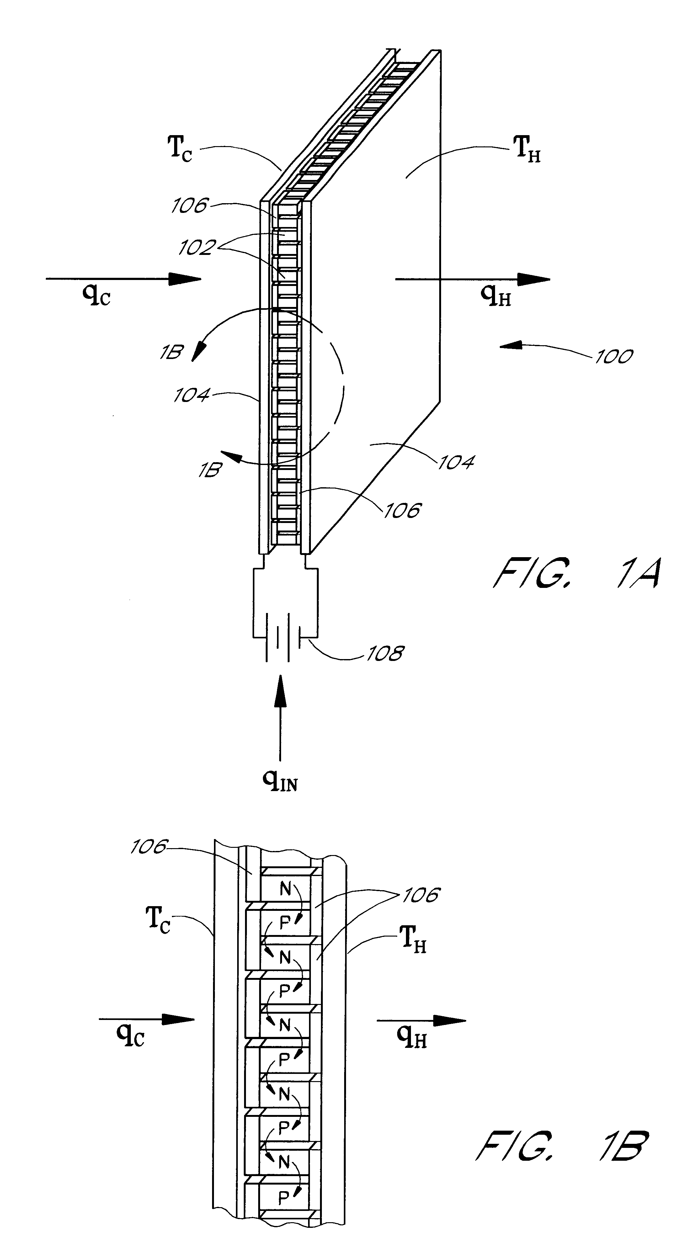
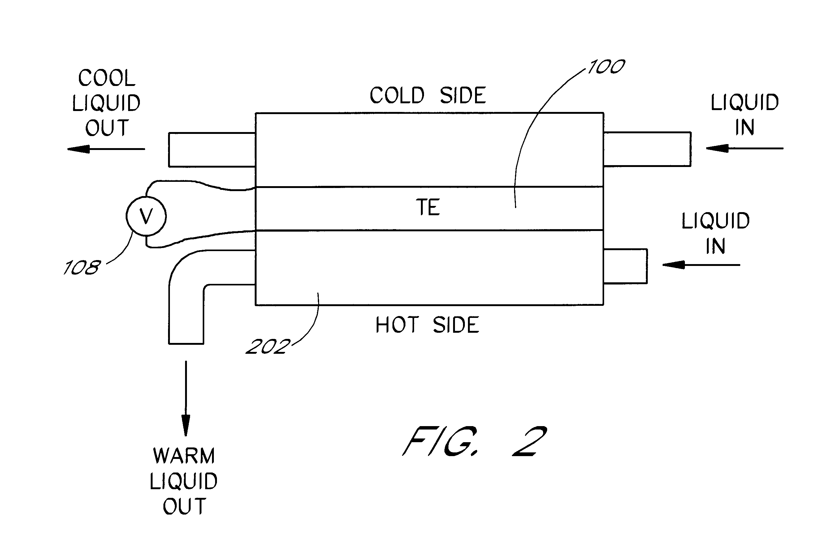
1. Field of the InventionThe present invention relates to improved thermoelectrics for producing heat and / or cold conditions with greater efficiency.2. Description of the Related ArtThermoelectric devices (TEs) utilize the properties of certain materials to develop a thermal gradient across the material in the presence of current flow. Conventional thermoelectric devices utilize P-type and N-type semiconductors as the thermoelectric material within the device. These are physically and electrically configured in such a manner that they provide cooling or heating. Some fundamental equations, theories, studies, test methods and data related to TEs for cooling and heating are described in H. J. Goldsmid, Electronic Refrigeration, Pion Ltd., 207 Brondesbury Park, London, NW2 5JN, England (1986). The most common configuration used in thermoelectric devices today is illustrated in FIG. 1. Generally, P-type and N-type thermoelectric elements 102 are arrayed in a rectangular assembly 100 bet...

Claims


Application Information

Patent Timeline
IPC IPC(8): F02G1/00F02G1/043F25B21/02H01L35/32H01L35/00H01L35/28H01L35/30F25B33/00
CPCF02G1/043F25B21/02H01L35/00H01L35/30H01L35/32F02G2254/11F25B33/00F25B2321/021H10N10/00H10N10/13H10N10/17
Inventor BELL, LON E.
Owner BSST INC
Learn More