Flexible toolbar and operating hydraulic circuit

a hydraulic circuit and flexible technology, applied in the direction of agricultural machinery, adjusting devices, agricultural tools and machines, etc., can solve the problems of affecting the desired universal adjustmentability, the inability or impracticality of mounting the inability to mount the applicator units to the toolbar frame, etc., to enhance the safety of the implement, and reduce the overall height of the implemen

Inactive Publication Date: 2004-01-13
CNH IND AMERICA LLC +1
View PDF13 Cites 65 Cited by
  • Summary
  • Abstract
  • Description
  • Claims
  • Application Information

AI Technical Summary

Benefits of technology

Thus, according to the present invention, the hydraulic cylinders which raise and lower the inner wings (called "inner wing fold cylinders") are operated under constant hydraulic pressure when the toolbars are placed in a field work position and then forced down for fertilizer application. This permits each wing section to continue to adjust to ground contour independently of the other wing section and the center section, while applying a substantially constant downward force on each wing section so that the coulters will penetrate even compacted, hard soil, and the applicator units will operate to deliver the liquid fertilizer consistently to the desired depth.
The hydraulic control circuit for the present invention operates in four primary is modes or cycles: (1) Unfold, (2) Work or Field Use, (3) End of Row Turn, and (4) Fold. All functions are accomplished by the operation of two main valves, a work valve and a transport valve, both located in the tractor cab for convenience and safe access. Assuming that the toolbar is in a horizontal position, having undergone an Unfold cycle from the transport position, the operator places the work hydraulic valve in a detent position. This position causes a main or center lift cylinder to retract, lowering the center frame section to operating (i.e., work or field use) position. The wings are then forced downwardly because the inner wing fold cylinders are extended. When the inner wing fold cylinders are fully extended, they are placed in a constant hydraulic pressure operating mode. That is, hydraulic pressure and flow from the tractor hydraulic pump is fed through a reducing / relieving valve and coupled to the inner wing fold cylinders to place them in the extended position with a constant hydraulic pressure in the butt or cylinder end. This applies a constant downward force on the wings, transferring weight from the center frame section to the wings, while permitting the wings independently to accommodate variations in the terrain. The constant downward force on the wings permits the applicator tools to operate at the desired depth, set by the wing gauge wheels, as the implement is drawn forward by the tractor. Operation in the Work mode may continue as the operator desires since the lever operating the directional Work valve is in a stable, detented position.
After the operator has completed the desired fertilizer application, and he wishes to move the implement to another location, the implement is placed in a transport configuration. To achieve this, the operator actuates the directional Transport valve to the Fold position. The hydraulic system causes the main lift cylinder to extend, raising the center section frame. In addition, the hydraulic system causes the outer wing fold cylinders to retract, folding the outer wing sections rearwardly about vertical axes. That is, the toolbars of the outer wing sections remain in the same general plane as the toolbars of the adjacent inner wing section. The inner wing sections are then folded over center by retraction of the inner wing fold cylinders until the wings rest on a wing support mounted to the center section frame. When the wings come to rest on the wing support, the inner wing sections extend inwardly, forming a delta shape with the center section frame; and the outer wing sections extend generally horizontally in a rearward direction. This reduces the overall height of the implement in the transport mode, and enhances the safety of the implement.
To place the implement from the transport position to the unfold position, the operator places the Transport valve in a second or unfold position. When the Transport valve is placed in the unfold position, the inner wing fold cylinders extend. The wings rotate outwardly relative to their associated hinge connections to the center section frame, so that the inner wing sections rotate downwardly. The inner wing sections achieve the desired horizontal position and actuate the limit switch to stop the unfolding of the inner wing sections. The outer wing sections are then rotated to extend outwardly, aligning with their associated inner wing sections. This unfold sequence reduces the overall height of the implement and reduces the possibility of interference from obstacles during the Unfold cycle.
Thus, the entire operation of the implement is controlled from the operator's position on the tractor using two tractor hydraulic selective control valves. This allows the operator to concentrate on tractor placement, tractor speed and row alignment, rather than manual procedures or distracting operations for the implement, while providing a winged fertilizer applicator implement having both inner wing sections and outer wing sections for increased operational width while reducing the overall transport height to manageable dimensions.

Problems solved by technology

Such an arrangement interferes with the desired universal adjustability in mounting the fertilizer applicator units (i.e., tools) with a wide variety of lateral settings.
In the past, the use of conventional hinges has made it impossible or impractical to mount the applicator units to the toolbar frame with universal adjustability of spacing yet maintaining uniform spacing between adjacent tools.

Method used


Image

  • Flexible toolbar and operating hydraulic circuit
  • Flexible toolbar and operating hydraulic circuit
  • Flexible toolbar and operating hydraulic circuit

Examples


Embodiment Construction

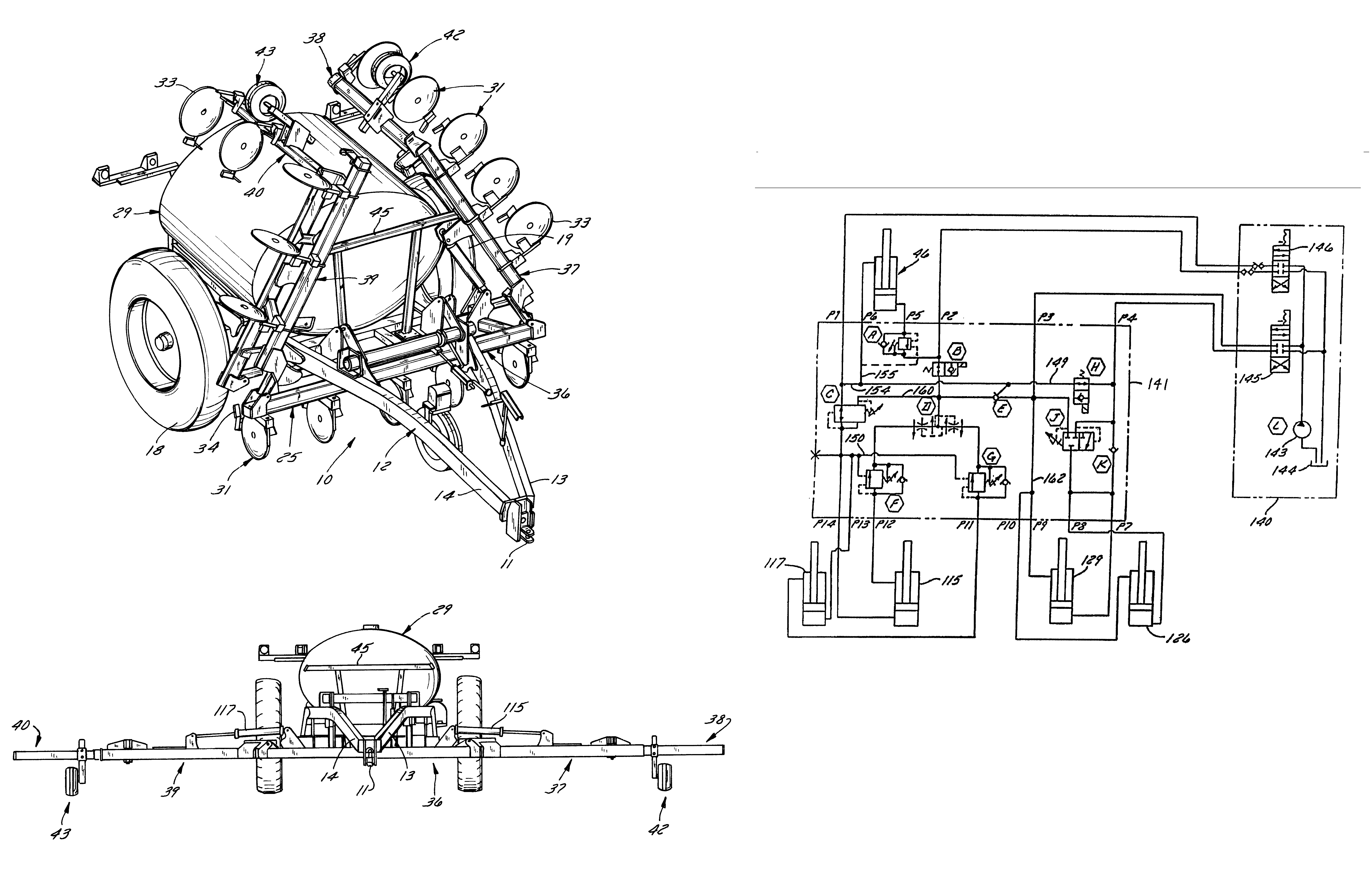
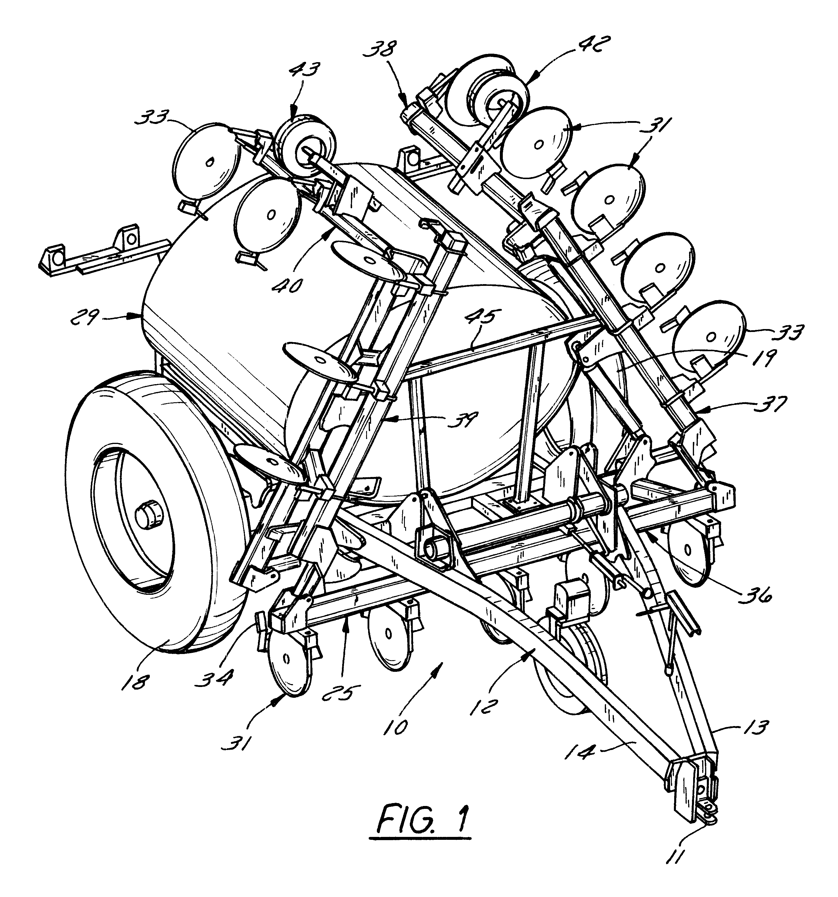
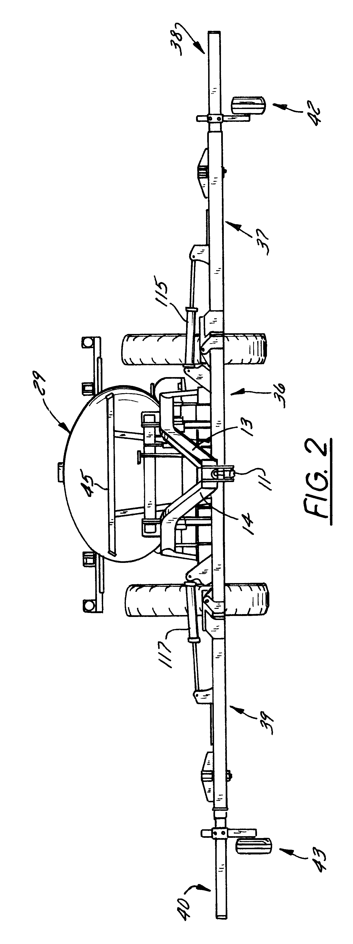
Referring to FIG. 1, reference number 10 generally designates a liquid fertilizer application implement which includes a conventional tractor hitch 11, and a main frame generally designated 12. The main frame, or pull frame as it is sometimes called, includes two main diverging tubular members designated 13 and 14, respectively. Tubular frame members 13, 14 are fixed at their forward ends to the hitch 11, and as they extend rearwardly, they are formed upwardly and they diverge. Thereafter, just behind the toolbar (designated 25), the frame members 13, 14 are fixed by plates (see 26 in FIG. 5) to a transverse frame member 16 which is part of a rectangular frame generally designated 17. A conventional axle assembly is mounted to two main support wheels 18, 19.

Referring particularly to FIG. 5, a tank support, the left half of which is seen in FIG. 5 and designated 21, is mounted to the horizontal frame 17.

A tank generally designated 29 in FIG. 1 is supported on the tank support 21 whic...


PUM


Abstract

A winged implement includes an hydraulic control circuit having two operator-controlled valves, including a work valve and a transport valve. Using only these controls, and without leaving the tractor cab, the operator can (1) fold the implement for transport; (2) unfold the wings; (3) place the implement in the field use position with substantial constant down pressure on the wings; and (4) raise the wings and center section to an intermediate position with the wings inclined upwardly for end row turns.

Description

The present invention relates to agricultural toolbars, and more particularly, it relates to agricultural toolbars which are flexible, permitting outboard wings to independently adjust vertically to follow variations in ground contour. The present invention is described in the context of an applicator for liquid fertilizer, although the structure and hydraulic operating circuit for the disclosed toolbar has broader application than liquid fertilizer applicators.Agricultural toolbars, particularly toolbars which are designed to apply liquid fertilizer, are typically designed so that the mounting bars on which the individual applicator units are fixed, are held or supported at a desired distance above the ground by adjustable depth gauging wheels. This is because it is highly desirable that fertilizer be placed at a constant depth beneath the surface of the soil so that the fertilizer is available to the plant for the various stages of development and growth of the plant.Up to a width...

Claims


Application Information

Patent Timeline
Patent Type & Authority Patents(United States)
IPC IPC(8): A01B63/00A01B73/04A01B73/00A01B63/32
CPCA01B63/32A01B73/044
Inventor MOSER, MARK K.JOHNSON, DARYL T.
Owner CNH IND AMERICA LLC
Why Eureka
Try Eureka