Microfluidic separators

a technology of microfluidic separator and separator plate, which is applied in the direction of flow mixer, diaphragm, water/sewage treatment, etc., can solve the problems of high tool-up cost for both of these techniques, inflexible and inability to meet the needs of rapid prototyping and manufacturing flexibility

Inactive Publication Date: 2004-01-13
NANOSTREAM INC
View PDF14 Cites 112 Cited by
  • Summary
  • Abstract
  • Description
  • Claims
  • Application Information

AI Technical Summary

Problems solved by technology

However, these techniques do not lend themselves to rapid prototyping and manufacturing flexibility.
Additionally, these techniques are limited to planar structures.
Moreover, the tool-up costs for both of these techniques are quite high and can be cost-prohibitive.
Generally, the mixing of fluids in a microfluidic system is problematic, since the fluid flow within these devices is not turbulent.
Such devices are complicated, requiring electrical contacts within the system.
Additionally such systems only work with charged fluids, or fluids containing electrolytes.
Finally, these systems require voltages that are sufficiently large that water is electrolyzed, which means bubble formation is a problem and samples cannot be easily collected without being destroyed.

Method used


Image

  • Microfluidic separators
  • Microfluidic separators
  • Microfluidic separators

Examples


example devices

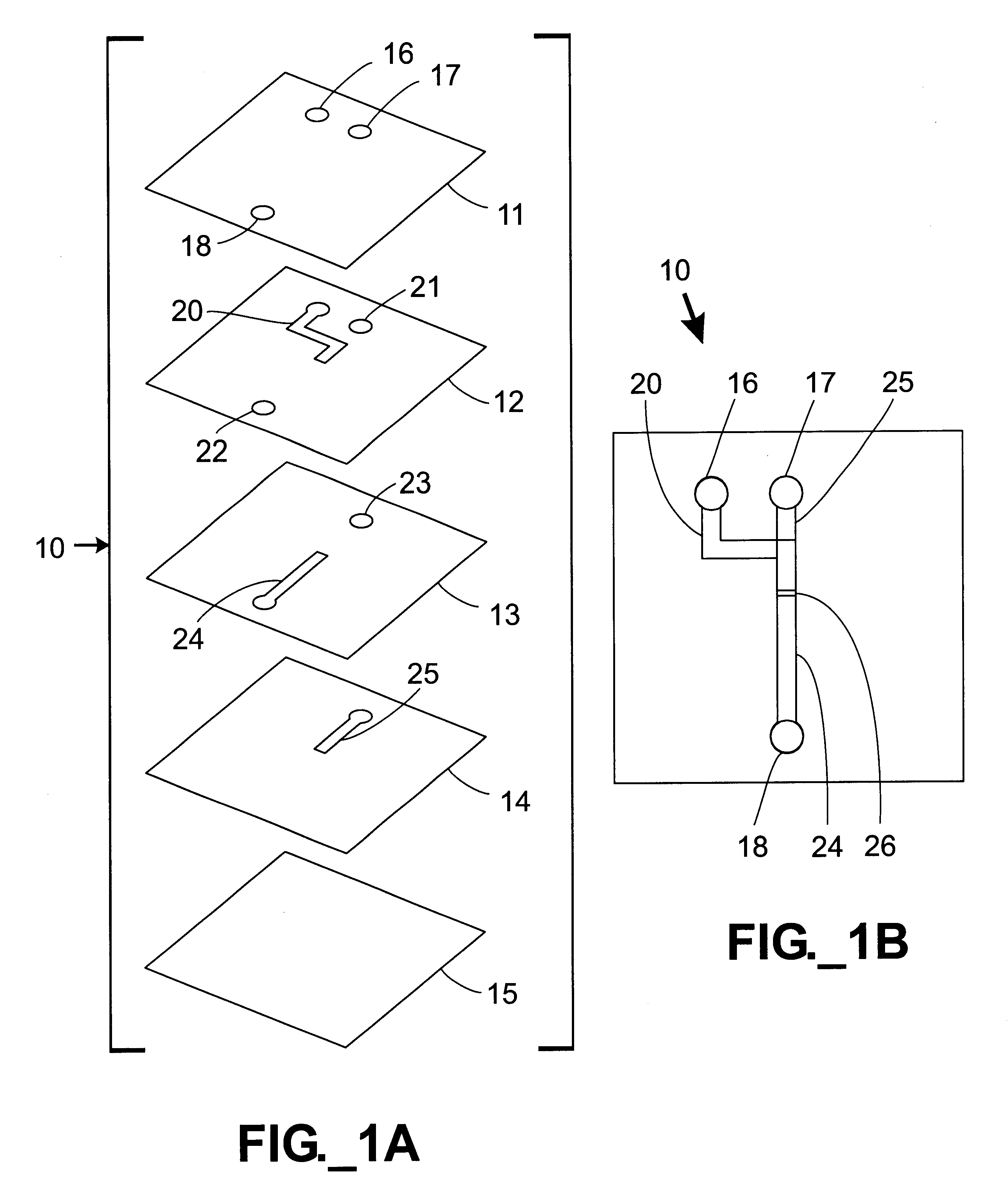
In the embodiment shown in FIGS. 1A-1B, a microfluidic mixing device 10 is constructed with sandwiched stencil layers. Referring to FIG. 1A, a microfluidic mixer 10 is constructed by sandwiching three stencil layers 12-14 and adhering them between substrates 11,15. The stencil layers 12-14 define various channels 20, 24, 25 and apertures 16-18, 21-23. Inlet ports 16,17 and an outlet port 18 are in the top device layer 11. The assembled device 10 is shown in FIG. 1B. In use, a first fluid is injected into inlet port 17, passes through through-holes 21, 23 in the layers 12 and 13 and enters the channel 25. A second fluid enters inlet port 16 and passes through channel 20. The two fluids meet at the overlap region 26 shown in FIG. 1B. At this point, the fluids are forced to converge into a single channel 24 defined in stencil layer 13. As the fluids meet and pass into channel 24, the top half of the channel 24 contains the second fluid and the bottom half contains the first fluid. The ...
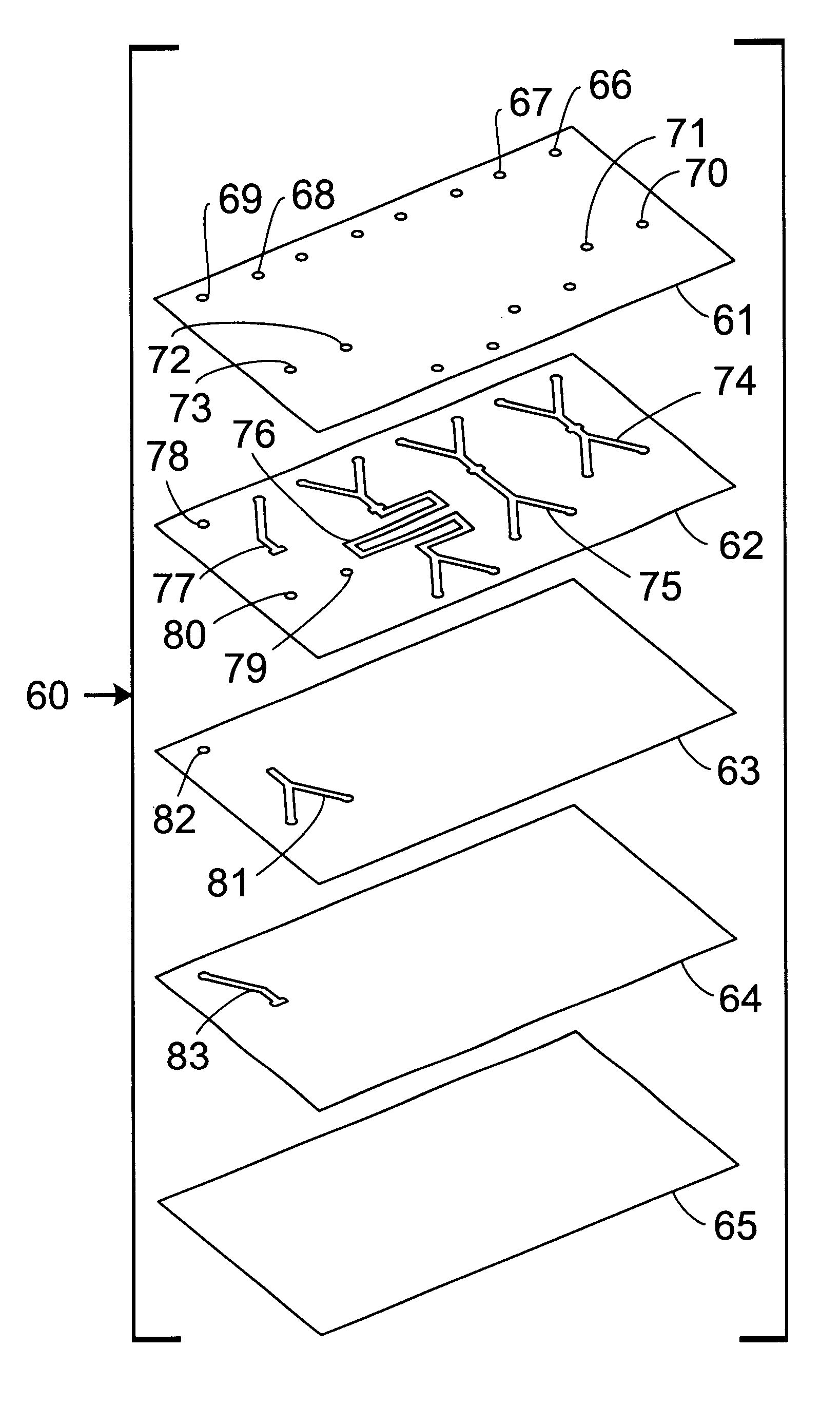
embodiment 90

Alternatively, a microfluidic mixer according to the present invention is shown. In this mixer 90, the inlet channels 77, 83 were constructed on different layers 62, 64 of a three dimensional structure. The inlet channels 77, 83 are in fluid communication at overlap region 95 where the two fluids to be mixed are forced to enter into an outlet channel 81, in this case located on a layer 63 intermediate to the layers 62, 64 defining the two inlet channels 77, 83. In this embodiment, at the overlap region 95 the interfacial contact area between the two fluids extends all the way across the width of the channel 81 and is fifteen times greater than in the previous mixer 91. In addition, the average distance that the molecules need to diffuse in order for mixing to occur is now two mils, rather than thirty mils as in the previous mixers 91-93.

This mixing behavior was demonstrated by performing a simple acid-base reaction within the mixers. In the mixer 90, a 0.1M NaOH solution was injecte...


PUM

PropertyMeasurementUnit
thicknessaaaaaaaaaa
thicknessaaaaaaaaaa
thicknessaaaaaaaaaa

Abstract

Microfluidic separators for separating multiphase fluids are described. Two or more microfluidic outlet channels within the device meet at an overlap region. The overlap region may be in fluid communication with an inlet channel. The inlet channel and each outlet channel are disposed within different layers of a three-dimensional device. Each channel is defined through the entire thickness of a stencil layer. A multiphase fluid flows through an inlet channel into an overlap region from where the separated phases can be withdrawn through the outlet channels.

Description

FIELD OF THE INVENTIONThe present invention relates to microfluidic devices and the manipulation of fluid flow within those devices. These devices are useful in various biological and chemical systems, as well as in combination with other liquid-distribution devices.BACKGROUND OF THE INVENTIONThere has been a growing interest in the manufacture and use of microfluidic systems for the acquisition of chemical and biological information. In particular, microfluidic systems allow complicated biochemical reactions to be carried out using very small volumes of liquid. These miniaturized systems increase the response time of the reactions, minimize sample volume, and lower reagent cost.Traditionally, microfluidic systems have been constructed in a planar fashion using silicon fabrication techniques. Representative systems are described, for example, by Manz, et al. (Trends in Anal. Chem. (1990) 10(5): 144-149; Advances in Chromatography (1993) 33: 1-66). These publications describe microfl...

Claims


Application Information

Patent Timeline
Patent Type & Authority Patents(United States)
IPC IPC(8): B01D17/00B01L3/00B01F13/00B01F5/06B81B1/00G01N35/00
CPCB01D17/00B01F13/0059B01L3/5027B81B1/002B01F5/0604B01D17/0208B01D17/08Y10T428/24744B01L3/502707B01L2300/0816B01L2300/0864B01L2300/0867B01L2300/0874B01L2300/0887B01L2300/165B01L2400/0406B01L2400/0487B81B2201/051G01N2035/00237G01N2035/00544Y10T428/24562Y10T137/8122Y10T137/2191Y10T137/2224B01F25/422B01F33/30
Inventor O'CONNOR, STEPHEN D.KARP, CHRISTOPH D.
Owner NANOSTREAM INC
Why Eureka
Try Eureka