Baler rotor reverser

a rotor reverser and rotor technology, applied in the field of balers, can solve the problems of time-consuming and difficult prior art of removing blockages by hand or with a lever or even with a powered sha

Inactive Publication Date: 2004-01-27
VERMEER MFG CO
View PDF20 Cites 17 Cited by
  • Summary
  • Abstract
  • Description
  • Claims
  • Application Information

AI Technical Summary

Benefits of technology

The reverser enables the operator to restore the baler to its working condition from the tractor seat. Being able to disengage the rotor from the rest of the machine enables the bale to be wrapped if a major blockage occurs. Also a

Problems solved by technology

The prior art of removing blockages by hand or with a lever

Method used


Image

  • Baler rotor reverser
  • Baler rotor reverser
  • Baler rotor reverser

Examples


Embodiment Construction

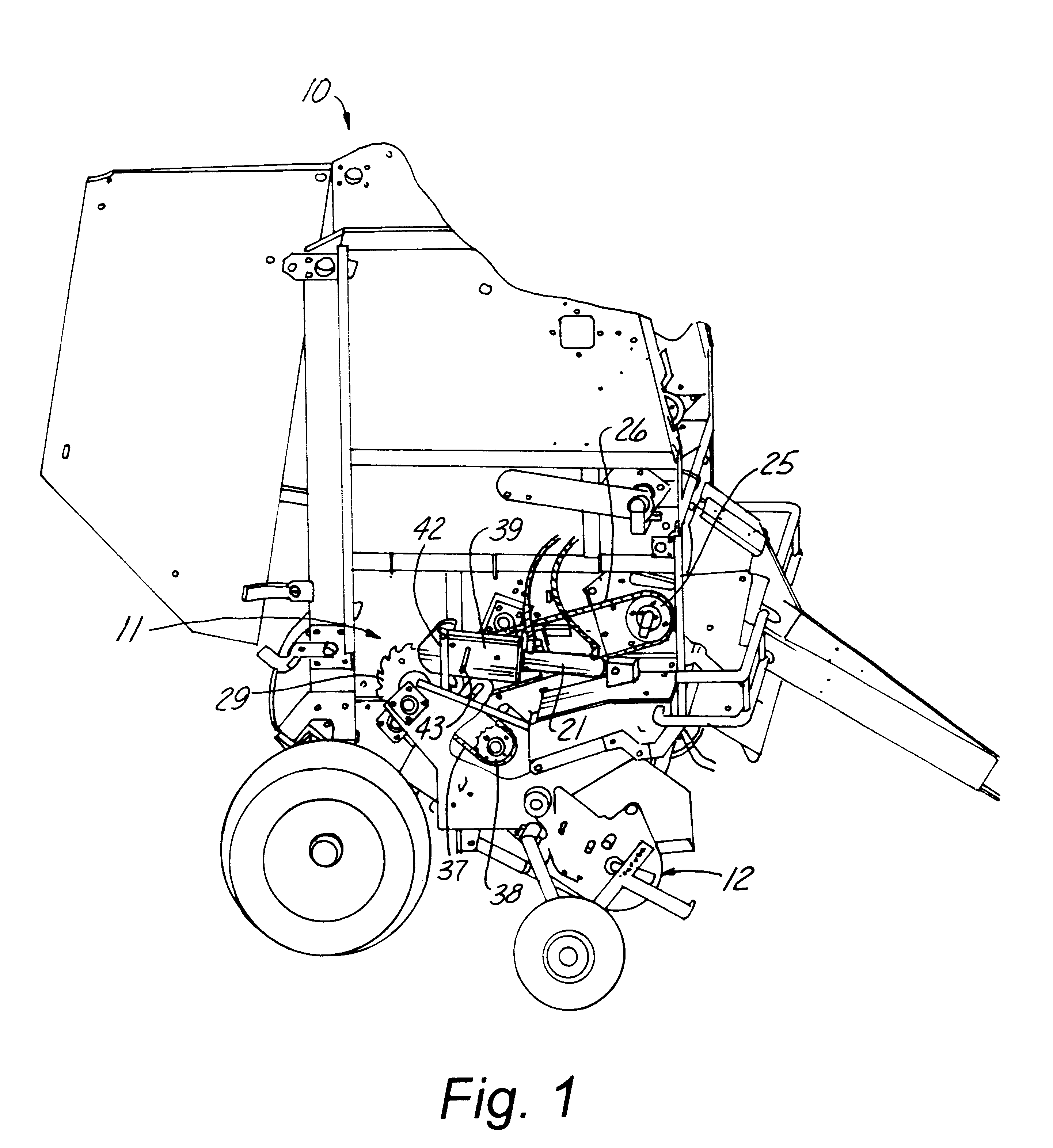
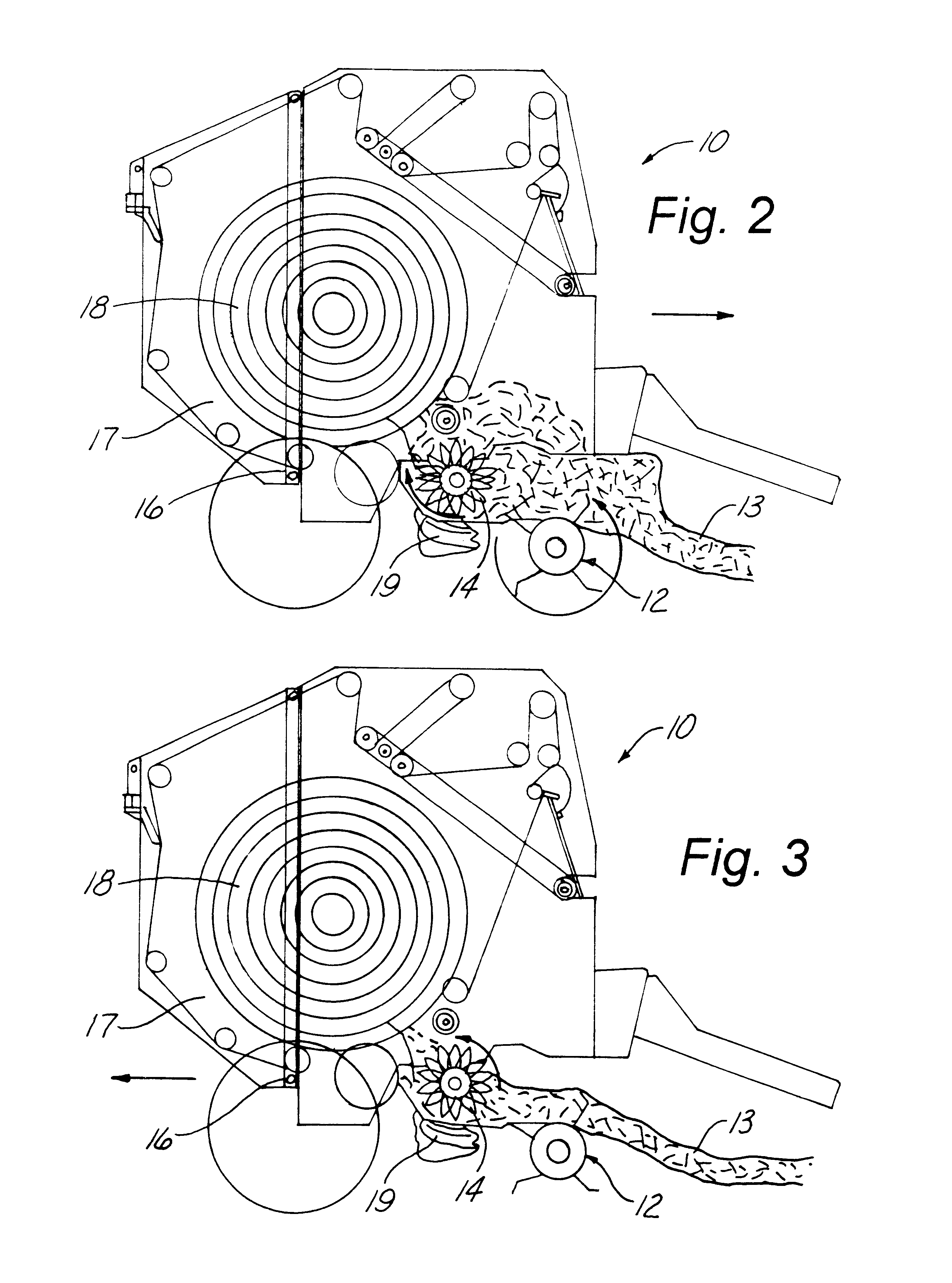
Referring now to the drawings, wherein like reference numerals designate identical or corresponding parts throughout the several views, FIG. 1 shows a baler (10) having a reverser (11) attached thereto. Referring now to FIG. 2, it is noted that a pickup reel (12) normally turns in a counter-clockwise direction as viewed in FIG. 2 to pull the windrow (13) of crop toward a rotor (14). This rotor (14) moves in a clockwise direction in FIG. 2 to pull the crop into a throat portion (16) and ultimately into a baling chamber (17) to form a bale (18). This rotor (14) has knives (19) which can extend into and between the fingers of the rotor (14) and, when extended, will cut the crop (13) as it is passed the blades (19) by rotor (14). These knives (19) can also be disengaged by being moved downwardly in the position shown in FIG. 2, for example as shown in U.S. patent application Ser. No. 09 / 498,527, filed Feb. 4, 2000, now abandoned.

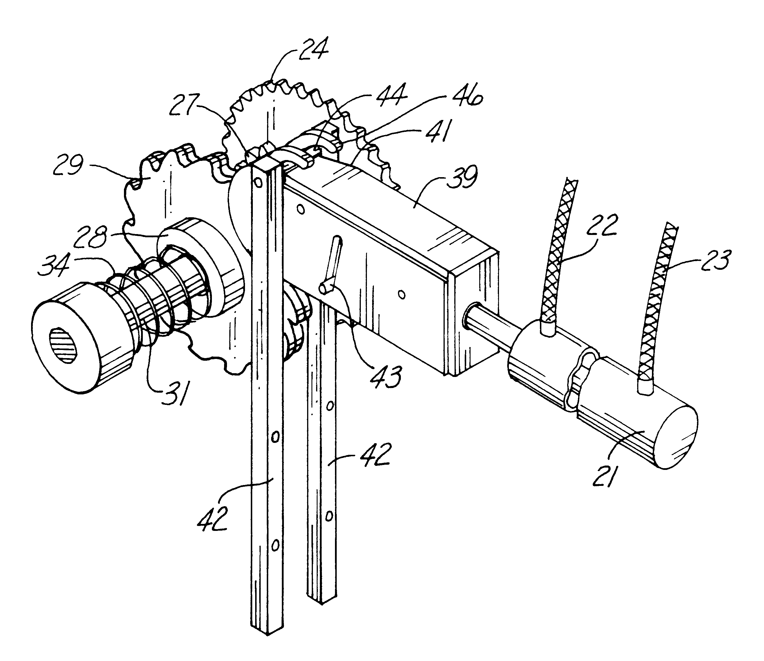
Referring now to FIGS. 1 and 4, it is noted that a hydraul...


PUM


Abstract

A reverser which, in a preferred embodiment, has a hydraulic cylinder supported by a chopper baler frame. The opposite end of the hydraulic cylinder is attached to the reverser driver. When activated by hydraulics on a tractor, the hydraulics will extend the cylinder, causing the sprockets to be disengaged. Further extension of the cylinder will cause the reverser driver to engage the reverser sprocket and turn the rotor backwards slightly. After full extension, the cylinder will then be retracted. This process can be repeated a couple of times in order to remove the blockage. The reverser enables the operator to restore the baler to its working condition from the tractor seat. Being able to disengage the rotor from the rest of the machine enables the bale to be wrapped if a major blockage occurs. Also a controlled reversing motion is beneficial, so over-reversing does not occur.

Description

CROSS-REFERENCE TO RELATED APPLICATIONSNot ApplicableSTATEMENT REGARDING FEDERALLY SPONSORED RESEARCH OR DEVELOPMENTNot ApplicableBACKGROUND OF THE INVENTION1. Field of the InventionThis invention relates to a baler and more particularly to one which has a rotor for assisting the chopping of the crop before it enters a baling chamber and which allows the rotor to be reversed when the baler becomes plugged.2. Description of the Related ArtIn a chopper baler, there is a pickup reel which picks a windrow of crop up from the ground and transfers it to a rotor which forces the crop through knives which can be selectively engaged to cut the crop. This rotor effectively transfers the crop from the pickup reel to a baling chamber where the crop is turned into a bale. In the preferred embodiment, this baler is one for making large round bales, but this invention is not limited to a round baler.From time to time, such a large amount of crop is moved from the reel to the rotor area that the cr...

Claims


Application Information

Patent Timeline
IPC IPC(8): A01F15/00A01F15/08A01F15/10
CPCA01F15/085A01F15/106A01F2015/108
Inventor NELSON, BRADLEY D.HOOD, WILLIAM A.WALKER, RYAN G.
Owner VERMEER MFG CO
Why Eureka
Try Eureka