Supercharge Your Innovation With Domain-Expert AI Agents!
Support device for supporting frames and other objects from a structure
Inactive Publication Date: 2004-01-27
COHEN MARK +1
View PDF17 Cites 14 Cited by
Summary
Abstract
Description
Claims
Application Information
AI Technical Summary
This helps you quickly interpret patents by identifying the three key elements:
Problems solved by technology
Method used
Benefits of technology
Benefits of technology
The present invention is directed to a support device for supporting an object from a wall or other structure. The support device is particularly useful for supporting frames and other types of objects from soft cubicle walls, corkboard, etc. The support provided is highly stable. The support device may readily be applied to or removed from a wall or other structure. The support device itself is characterized by its ease of use and effectiveness. Objects may be supported from soft cubicle walls by the support device without damaging the wall or permanently marking the wall. Repositioning of the support device is accomplished simply and quickly.
Problems solved by technology
People often encounter difficulties when attempting to hang frames and other types of objects from cubicle walls.
Conventional hanger hardware is inappropriate and ineffective in such an environment.
Method used
Image
Click on the blue label to locate the original text in one second.
Reading with bidirectional positioning of images and text.
Examples
Embodiment Construction
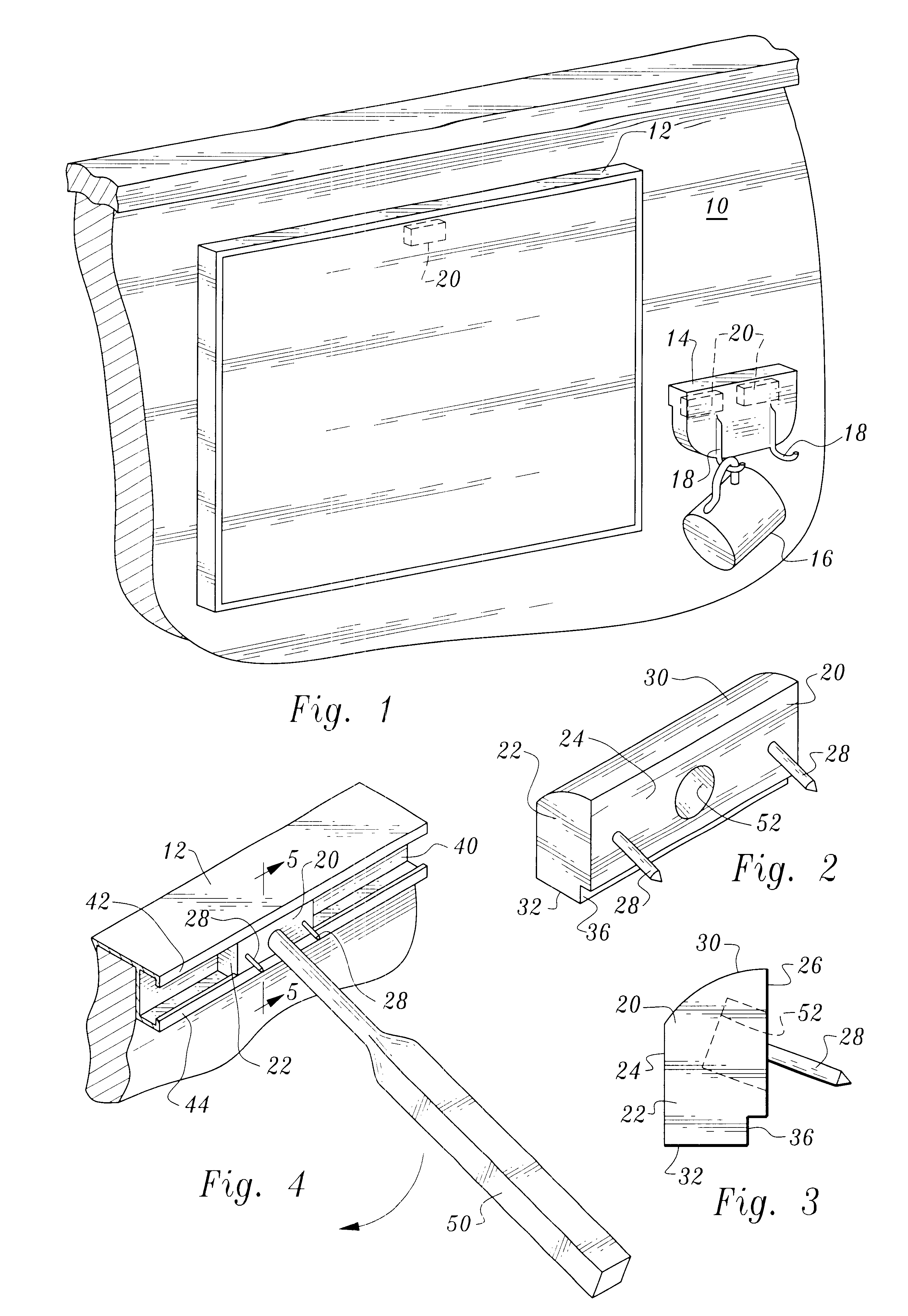
Referring now to FIG. 1, a soft cubicle wall 10 of conventional construction is shown. Typically such walls are comprised of an inner soft porous core and outer fabric surfaces. In FIG. 1 the wall 10 supports two objects, a picture frame 12 and a cup holder 14, the latter in turn holding a cup 16 from one of the hooks 18 of the cup holder.
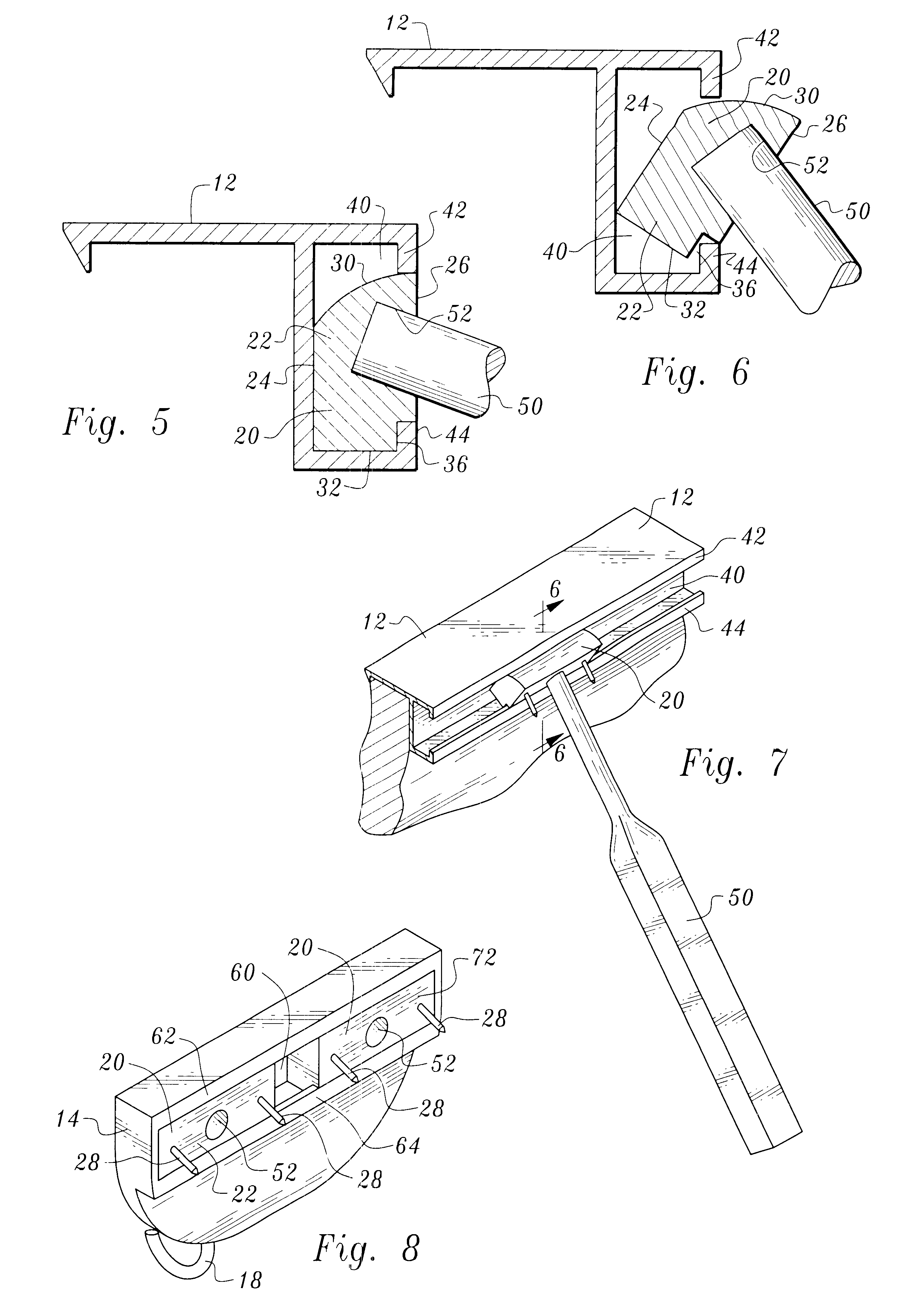
A support device 20 is employed to support the frame from the cubicle wall. Two such support devices 20 are utilized to support the cup holder 14.
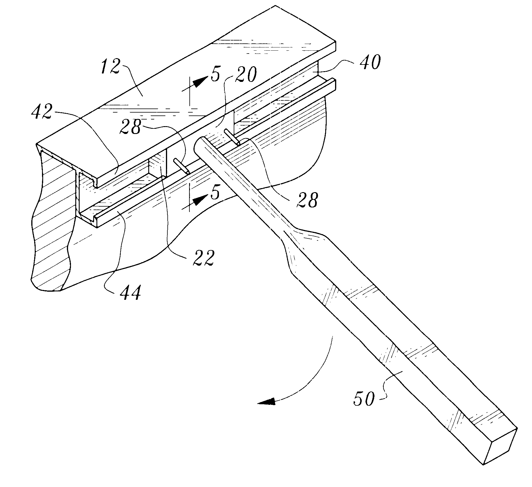
Referring now to FIGS. 2-7, the support device 20 includes a support member 22 of integral construction, preferably formed of plastic or the like. The support member is relatively rigid, suitably being a molded plastic part.
Support member 22 has a planar front support member surface 24 and a planar rear support member surface 26. The rear support member surface 26 is for positioning in face-to-face relationship with the wall 10.
Two spaced pin members 28 are affixed to the support member for piercing and e...
PUM
Abstract
A support device for supporting a frame or other object from a wall or other structure. The support device includes a support member placed in a recess of an object and releasably frictionally retained in place. At least one canted pin member projects from the support member for entering the structure.
Description
This invention relates to a device which is particularly applicable to hang or support frames and other types of objects from cubicle walls and other types of walls. The invention is particularly useful when employed with fabric or other soft wall surfaces of the types commonly employed in office cubicles.People often encounter difficulties when attempting to hang frames and other types of objects from cubicle walls. Conventional hanger hardware is inappropriate and ineffective in such an environment.A search directed to the present invention located the following United States Patents: U.S. Pat. No. 4,179,089, issued Dec. 18, 1979, U.S. Pat. No. 5,199,681, issued Apr. 16, 1993, U.S. Pat. No. 6,186,466, issued Feb. 13, 2001, U.S. Pat. No. 5,588,629, issued Dec. 31, 1996, U.S. Pat. No. 5,138,780, issued Aug. 18, 1992, U.S. Pat. No. 4,279,087, issued Jul. 21, 1981, U.S. Pat. No. 3,871,121, issued Mar. 18, 1975, and U.S. Pat. No. 5,464,185, issued Nov. 7, 1995.The invention disclosed a...
Claims
Application Information
Patent Timeline
Application Date:The date an application was filed.
Publication Date:The date a patent or application was officially published.
First Publication Date:The earliest publication date of a patent with the same application number.
Issue Date:Publication date of the patent grant document.
PCT Entry Date:The Entry date of PCT National Phase.
Estimated Expiry Date:The statutory expiry date of a patent right according to the Patent Law, and it is the longest term of protection that the patent right can achieve without the termination of the patent right due to other reasons(Term extension factor has been taken into account ).
Invalid Date:Actual expiry date is based on effective date or publication date of legal transaction data of invalid patent.
