Microvalve controller for pneumatically contoured support

Inactive Publication Date: 2004-01-27
KONGSBERG AUTOMOTIVE SP ZOO
View PDF27 Cites 85 Cited by
  • Summary
  • Abstract
  • Description
  • Claims
  • Application Information

AI Technical Summary

Problems solved by technology

One problem with systems for pneumatically contouring support surfaces such as vehicle seats, furniture seats and pneumatically controlled beds is how to interconnect valve control units with pressurized expandable chambers and with a pressure source in a compact and an efficient manner.

Method used


Image

  • Microvalve controller for pneumatically contoured support
  • Microvalve controller for pneumatically contoured support
  • Microvalve controller for pneumatically contoured support

Examples


Embodiment Construction

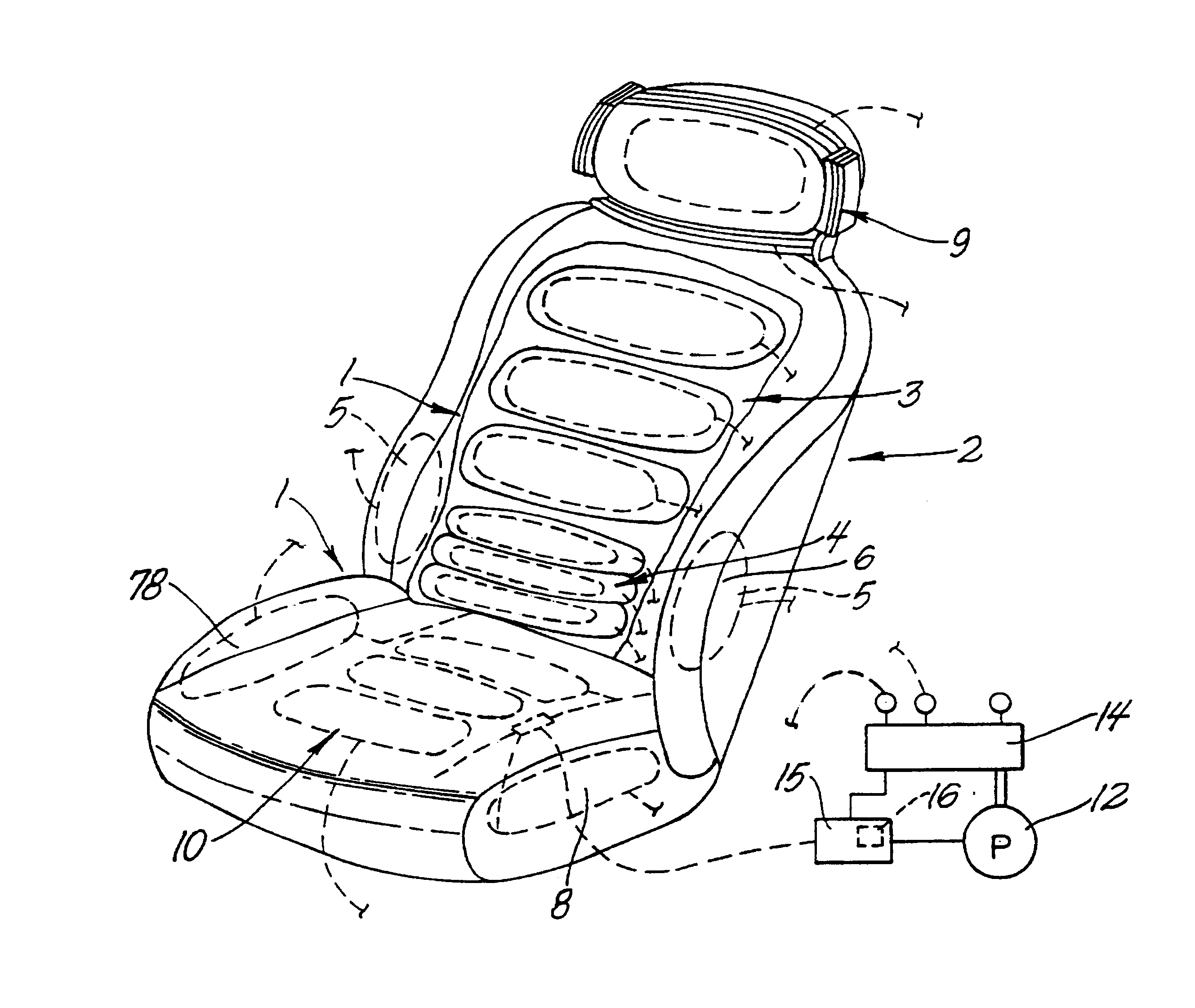
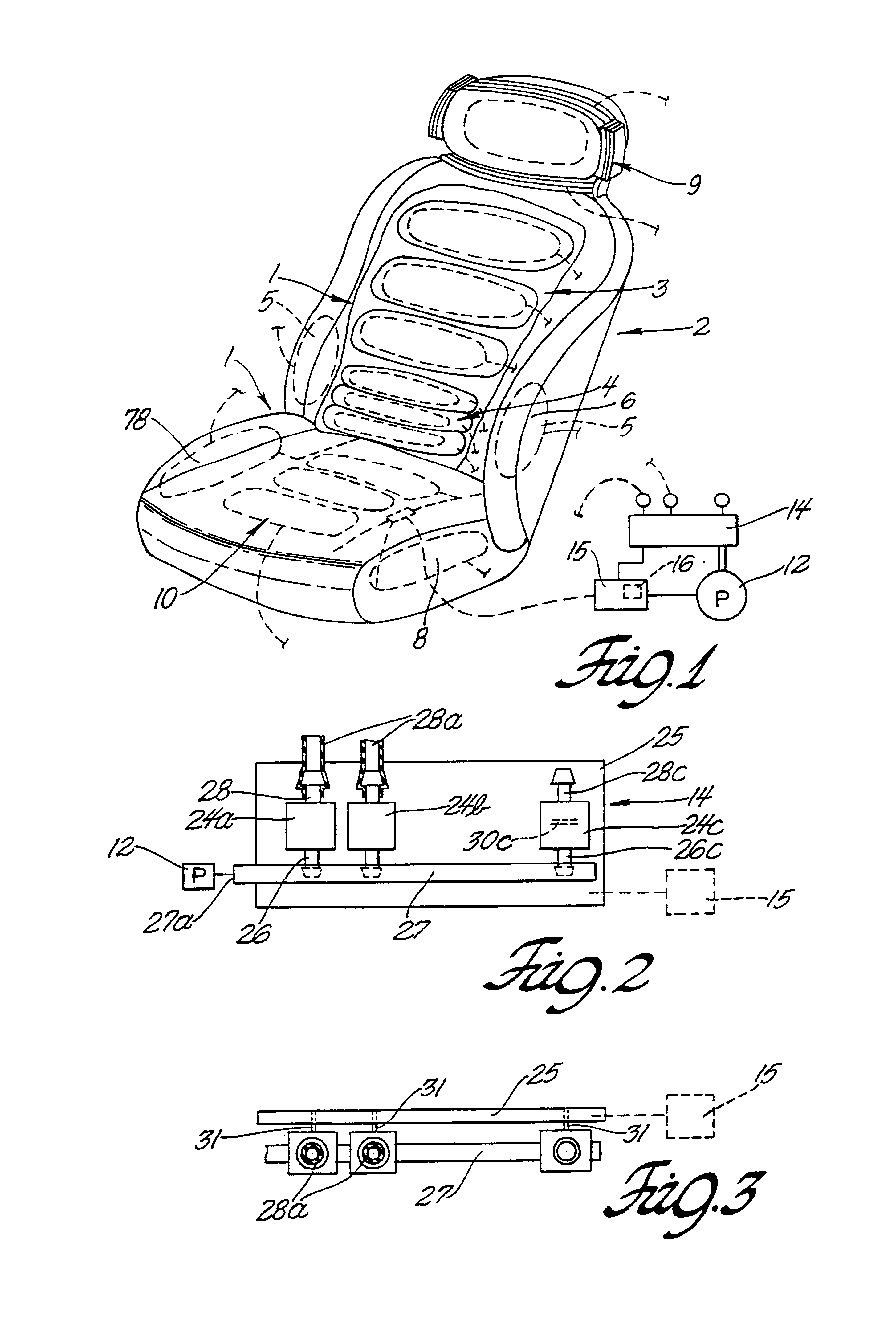
A series of air cells or bladders 1 are placed at strategic locations about the contour of an automotive seat 2 as shown in FIG. 1. The air cell placement is selected to coincide with key pressure points on the body of an occupant of the seat.

In particular, plural cells 3 are positioned in the thoracic region while plural cells 4 are combined in the lumbar region. To further facilitate the adjustment of the seat, pairs of cells 5, 6, 7 and 8 are positioned at either side of the back and seat as well as the front and back of the thighs respectively. Each of these cells is in direct contact with the body to provide the control system with information, which may be related to the comfort of the user.

In addition to the pairs of cells that are provided to adjust the comfort of a user, in accordance with the present invention a plurality of air cells 9 are formed in the headrest and a plurality of air cells 10 are provided in the seat bottom.

The cells are connected to a source of pressuri...


PUM


Abstract

A pneumatic support system and controller combination including pressurizable expandable chambers (1); a source of pressure and an exhaust characterized by: a unitary manifold assembly (14) including a circuit board (25); a manifold (27) and one or more microvalves (24) having a silicon based valve actuator responsive to a signal for controlling flow from said manifold with respect to one or more expandable chambers.

Description

This invention relates to fluid flow controllers for pneumatically contoured supports and more particularly to low energy consumption fluid flow control systems for use in controlling fluid flow in a pneumatically operated system having expandable fluid chambers with a contoured support surface and wherein the fluid control systems include a microvalve having a condition responsive actuator for controlling a relatively large volume of flow through a valve unit.BACKGROUND OF INVENTIONU.S. patent application Ser. No. 08 / 808,511, filed Feb. 27, 1997, discloses a pneumatically controlled seating system in which an electronic control module selectively controls energization of a valve unit for controlling air flow from a pressure source to a plurality of pressurizable expandable fluid chambers or air cells.The valve unit is a low energy consumption valve that is opened and closed by a valve actuator having a low consumption of power during operation of the system. One suitable valve for ...

Claims


Application Information

Patent Timeline
Patent Type & Authority Patents(United States)
IPC IPC(8): A47C7/46A47C7/14B60N2/02B60N2/44F15C5/00A47C27/08A47C27/10B60N2/90F16K99/00
CPCA47C4/54A47C7/14A47C7/467A47C27/082A47C27/083A47C27/10B60N2/0244B60N2/4415F15C5/00F16K99/0001F16K99/0011F16K99/0036F16K99/0042F16K99/0044F16K99/0051F16K2099/0071F16K2099/0082F16K2099/009B60N2/914B60N2/0224B60N2/665
Inventor DANIELS, GEORGE F.RHODES, RICHARD D
Owner KONGSBERG AUTOMOTIVE SP ZOO
Why Eureka
Try Eureka