Near-zero propagation-delay active-terminator using transmission gate

a technology of transmission gate and active terminator, which is applied in the field of transmission lines, can solve the problems of latch tripping, the clock driver is unable to drive the double load without serious signal distortion, and the expansion of the system can also create problems

Inactive Publication Date: 2004-02-03
DIODES INC
View PDF18 Cites 30 Cited by
  • Summary
  • Abstract
  • Description
  • Claims
  • Application Information

AI Technical Summary

Problems solved by technology

However, as clock rates rise above 100 MHz, metal traces on circuit boards behave as transmission lines, exhibiting reflections, undershoot, overshoot, and ringing that distort signals.
Expandability of systems also can create problems.
However, when the user later expands the memory to 36 memory chips the clock driver is unabl

Method used


Image

  • Near-zero propagation-delay active-terminator using transmission gate
  • Near-zero propagation-delay active-terminator using transmission gate
  • Near-zero propagation-delay active-terminator using transmission gate

Examples


Embodiment Construction

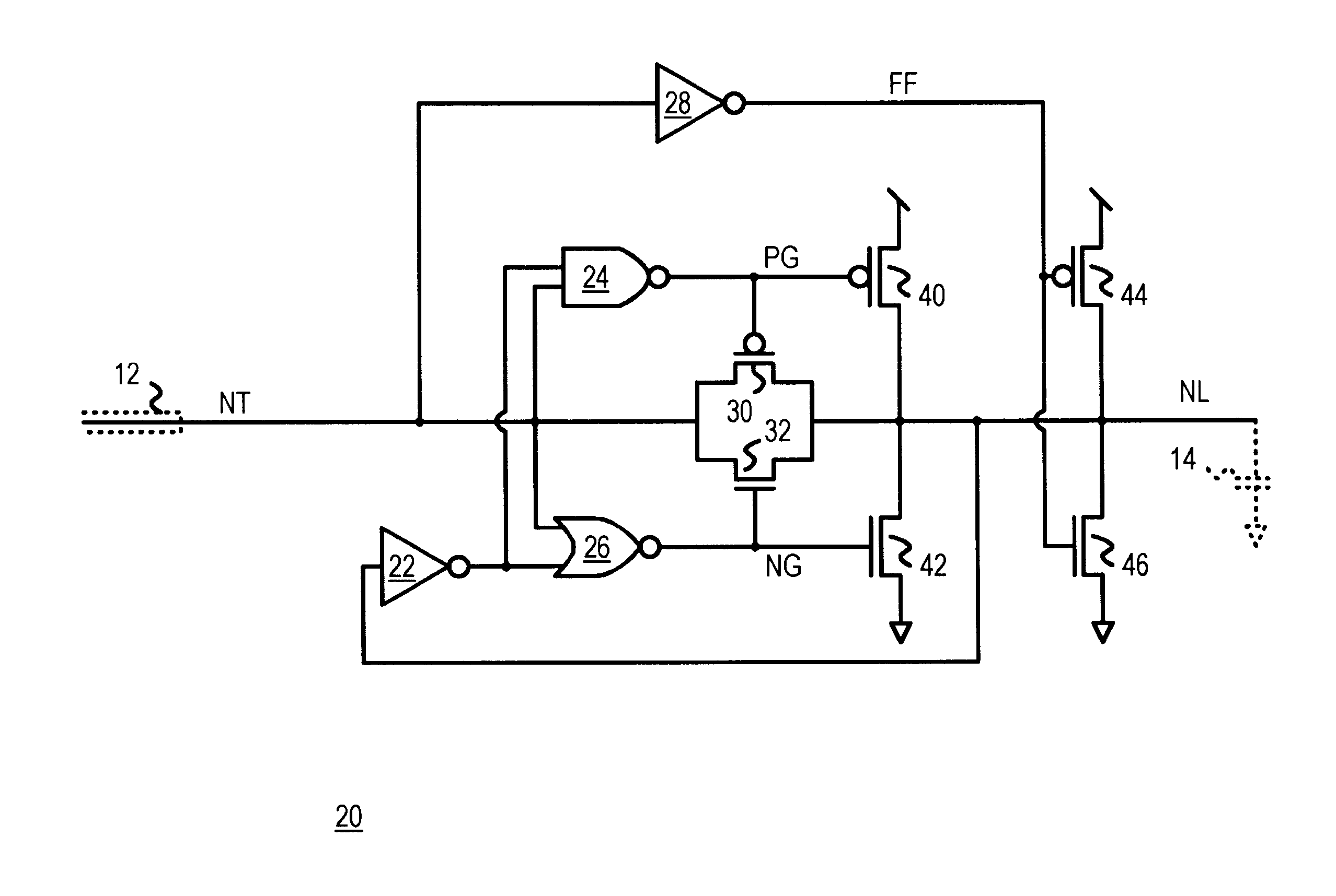
Several other embodiments are contemplated by the inventor. For example the buffer can be used as a bi-directional transceiver for bi-directional data transfer. Another buffer, connected in the reverse direction, can be used for read operation. Read / Write command / status signals can be input as enable signals to the buffers to control the direction of data flow.

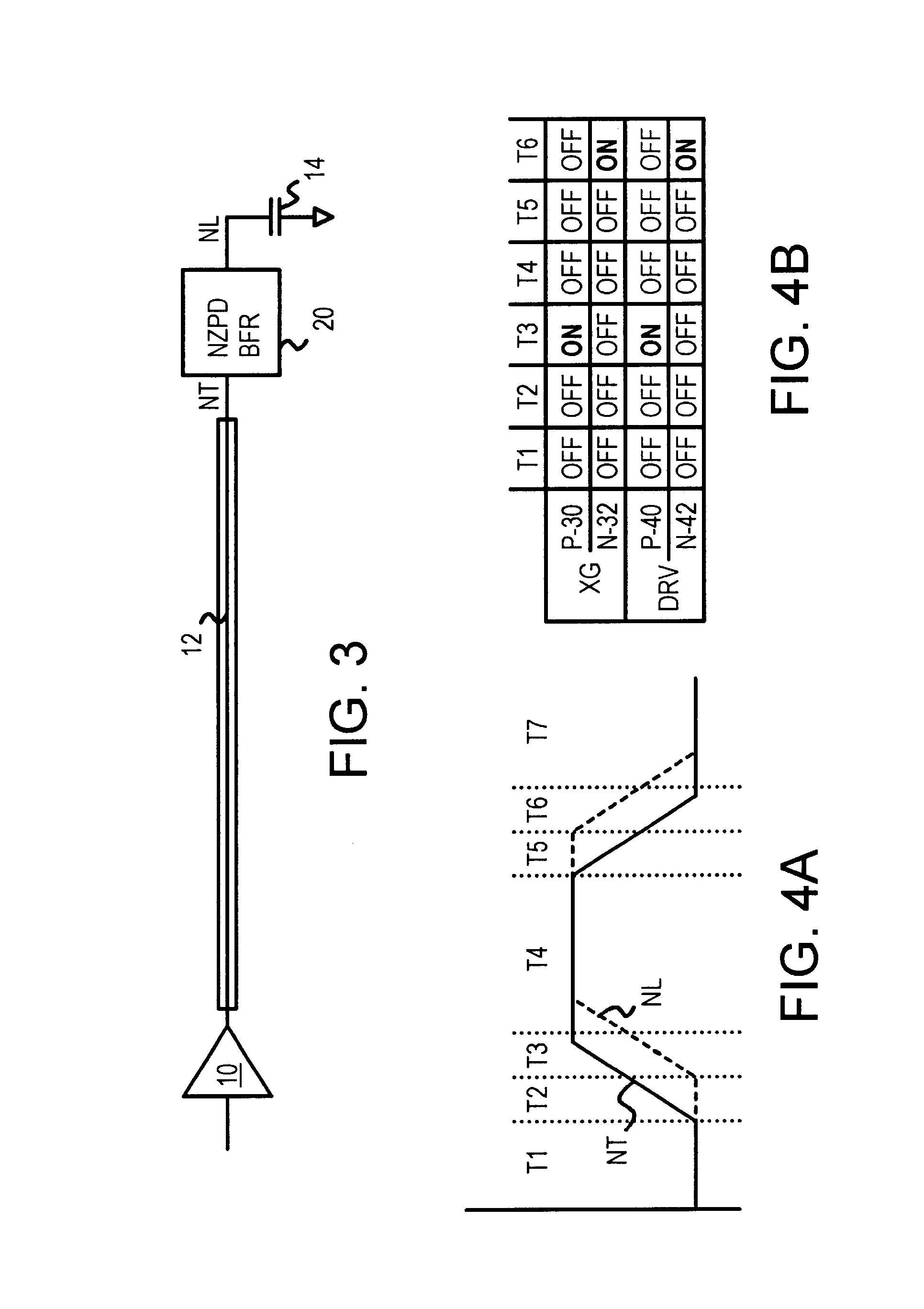
Additional termination could be added, such as a series resistor at the near end of the transmission line, or a resistor to ground or another fixed voltage at the input or output to buffer 20. A clocked latch could be substituted, using enable signal ENA to open the input to the latch, or using some other signal such as a transition detector on input node NT. Many kinds of latches, cross-coupled devices, etc. could be substituted. Inverters 52, 54 of FIG. 8 could replace latching transistors 44, 46 in the embodiments of FIGS. 5-7 without using the enable circuit of FIG. 8. Rather than use latches, logic can drive output nodes ...


PUM


Abstract

A transmission line is terminated by a buffer. The buffer isolates a load from the transmission line using a transmission gate. The transmission gate is turned off and does not conduct most of the time, but turns on when a transition is detected on the transmission line, allowing the transmission line to directly drive the load for a short time. Once the load is switched beyond a logic threshold voltage, the transmission gate is again turned off and a latch or latching transistors driven by the transmission line continue to drive the isolated load to power or ground voltages. Driver transistors are also enabled when the transmission gate is turned on, driving either the output (load) node or the input (transmission line) node with the new data. Feedback from the output node disables the transmission gate and driver transistors once the output has been driven past the logic threshold.

Description

BACKGROUND OF INVENTIONThis invention relates to transmission lines, and more particularly to active terminator buffers with positive feedback.Performance of electronic systems can be improved by increasing clock rates. However, as clock rates rise above 100 MHz, metal traces on circuit boards behave as transmission lines, exhibiting reflections, undershoot, overshoot, and ringing that distort signals.Expandability of systems also can create problems. For example, a personal computer may be shipped with a base memory having 18 memory chips driven by a clock line. The clock driver is able to drive the 18 memory chips without serious signal distortion. However, when the user later expands the memory to 36 memory chips the clock driver is unable to drive the doubled load without serious signal distortion.FIG. 1 shows a transmission line driving a load. Driver 10 drives one end of transmission line 12, which can be a metal trace on a circuit board, or a cable or other connection to anot...

Claims


Application Information

Patent Timeline
IPC IPC(8): H03K19/00H03K17/16H03K19/017H03K19/01H03K17/04H03K17/042
CPCH03K17/04206H03K17/167H03K19/0013H03K19/01721
Inventor YEN, YAO TUNG
Owner DIODES INC
Why Eureka
Try Eureka