Information dependent data transmission for pilot protective relays

a technology of information dependent data and relays, which is applied in the direction of transmission systems, instruments, code conversion, etc., can solve the problems of inability to use more sophisticated protocols such as v.90, inability to guarantee delivery time, and inability to meet the requirements of the customer

Inactive Publication Date: 2004-02-03
ABB INC
View PDF8 Cites 11 Cited by
  • Summary
  • Abstract
  • Description
  • Claims
  • Application Information

AI Technical Summary

Problems solved by technology

Using more sophisticated protocols such as V.90 is not feasible because of delays associated with such modems.
The delays give rise to a delivery time that cannot be guaranteed and which is not acceptable if trip decisions are to be made in a time period that is less than one cycle of the power line frequency.
The signals are, however, not relatively stationary in abnormal operation and the simple expedient of sending the "difference from the norm" will not increase the information throughput for the same signaling bandwidth.

Method used


Image

  • Information dependent data transmission for pilot protective relays
  • Information dependent data transmission for pilot protective relays
  • Information dependent data transmission for pilot protective relays

Examples


Embodiment Construction

)

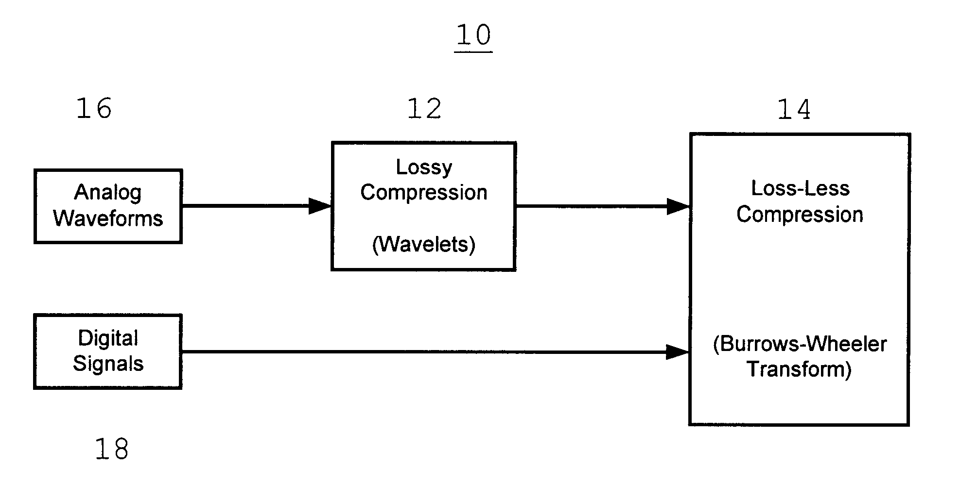
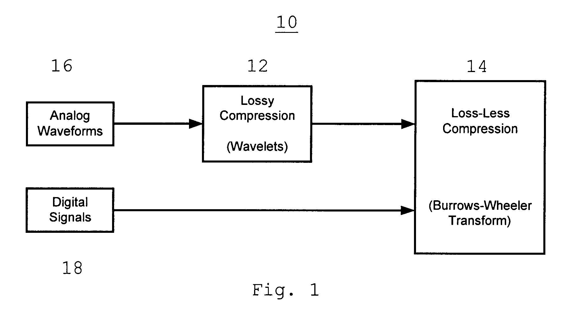
The present invention is described below in connection with the exchange of differential current and voltage data between two pilot protective relays. In this example the two relays exchange information about the three electrical current channels and the three voltage channels at the rate of four samples per quarter cycle per channel. Thus the two relays exchange a total of 24 data samples in each quarter cycle.

The current and voltage data samples exchanged between the two relays are the dynamic transient changes or differences in the current and voltage. The present invention allows the transmission of these samples in a manner such that all required information is promptly made available to both relays without compromising the integrity of the dynamic transient data. The present invention makes use of data compression and improves information throughput independent of the transmission technique.

As is well known data compression is divided into two main categories: Lossy and Lossl...


PUM


Abstract

Waveform information is transmitted from the ends of a protection zone by first compressing the information using a lossy compression technique such as wavelets and then compressing the lossy compressed waveform information using a loss-less compression technique such as the Burrows-Wheeler transform. Status information is transmitted from the ends of the protection zone by compressing that information using the loss-less technique. The time for transmission can be less than, equal to or greater than the time for one cycle of the power line frequency.

Description

This invention relates to pilot protective relays and more particularly to the communication of status and waveform information from two ends of a protection zone.DESCRIPTION OF THE PRIOR ARTAs is well known pilot protective relays are used to provide protection for high-voltage electrical transmission lines. Those sections of the transmission lines that have pilot protective relays located at each end are known as the protection zones. It is the function of the pilot relays to identify faults in the protection zone and initiate line isolation by way of the tripping of the appropriate circuit breakers. To provide this protection the pilot protective relays monitor the AC voltages and currents at the transmission line terminals and coordinate operation by communicating status and waveform information from the two ends of a protection zone. Generally, such differential protection performance improves as the amount of information increases.As used herein waveform information refers to ...

Claims


Application Information

Patent Timeline
Patent Type & Authority Patents(United States)
IPC IPC(8): H03M7/30H02H7/26
CPCH03M7/30H02H7/261
Inventor LOCASALE, THOMAS M.ELSTON, JOEL A. B.JOUNY, ISMAIL I.
Owner ABB INC
Why Eureka
Try Eureka