Dosing device for bulk materials

a technology for bulk materials and dosing devices, which is applied in the direction of movable measuring chambers, liquid handling, instruments, etc., can solve the problems of affecting the uniformity of dosing, the difficulty of continuous feeding of supply containers, and the difficulty of ensuring the accuracy of dosing, so as to achieve convenient access and uniform throughflow

Inactive Publication Date: 2004-02-10
SCHENCK PROCESS GMBH
View PDF16 Cites 9 Cited by
  • Summary
  • Abstract
  • Description
  • Claims
  • Application Information

AI Technical Summary

Benefits of technology

In view of the above it is the object of the invention to provide a dosing device that is easily accessible and that assures a uniform throughflow of all bulk materials through the bulk material containers with most simple structural components.
The invention has the advantage that by using a vertical stirring mechanism, the marginal areas and the bottom areas of the bulk material container having a rotational symmetry all the way to the outlet opening are reachable by stirring mechanism wings. Thus, no bulk material remainders can adhere or spoil. Simultaneously, a homogeneous bulk material throughflow is achievable because the uniform rotational motion of the wings of the stirring device across the direction of the force of gravity reaches all container areas in the same force direction, whereby the flow velocity is uniformly influenced in all areas.
The invention has further the advantage that due to the stirring device coupling the fixed installed stirring device areas and container areas do not need to be disassembled with the aid of tools when cleaning or service operations are necessary so that prolonged down times of the dosing device are avoidable. At the same time the discharge device with a portion of the bulk material container is horizontally laterally removable due to the stirring device coupling. As a result, advantageously no additional vertical assembly space is required for dosing components mounted in the direction of the gravity force. Furthermore, the stirring coupling permits driving both stirring sections through the force transmitting coupling with but one stirring drive so that, advantageously, a separate stirring device drive for the removable stirring device section and container part is obviated.
According to a special embodiment of the invention the discharge apparatus is horizontally slidable into a discharge head that is mounted in a fixed position. This feature advantageously permits separating structural components which require service or cleaning, in a simple manner from the side of the dosing device that faces away from the process. Such separating is achievable without any substantial assembly effort and expense.

Problems solved by technology

Thereby, problems may occur during the continuous feeding from the supply container into the conveyor, particularly in connection with bulk materials that hardly flow, stick together and form bridges.
However, there is no connection between the stirring mechanism and a supply container attachable above, so that it is possible that the bulk material sticks to the supply container, or a separate stirring mechanism must be arranged there.
Detaching of this type of construction is relatively labor intensive when service or cleaning operations must be done.
However, hardly flowable bulk materials can adhere or form bridges in the supply container, whereby a uniform dosing is impaired.
Particularly, it is frequently not possible with such horizontal stirring mechanisms when dosing strongly adhering powders, to separate these all over from the margin and bottom areas because the stirring components cannot reach these areas.
Bulk materials such as groceries remaining in these areas can easily over-age during prolonged dosing durations or they may harden or they may impair the dosing operation in another manner so that intermediate service or cleaning operations are necessary.

Method used


Image

  • Dosing device for bulk materials
  • Dosing device for bulk materials
  • Dosing device for bulk materials

Examples


Embodiment Construction

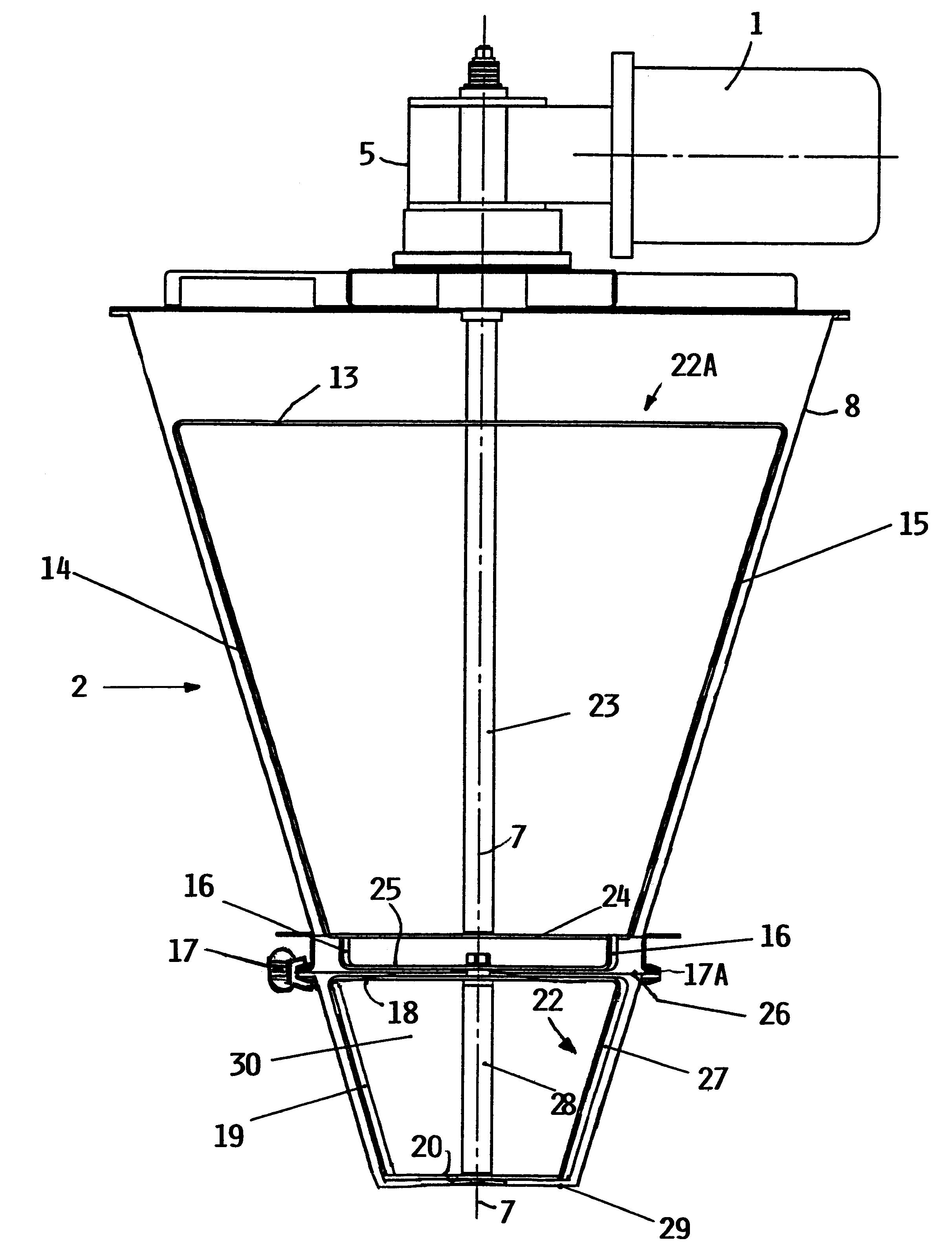
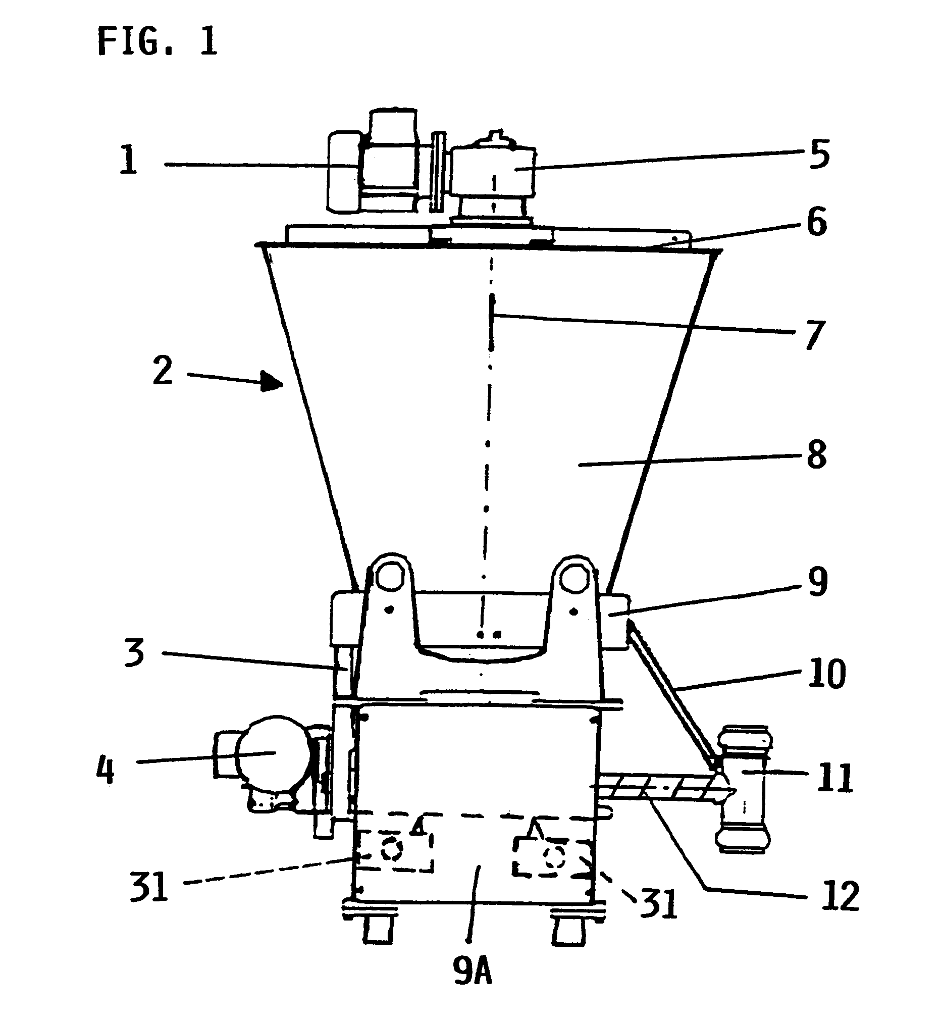
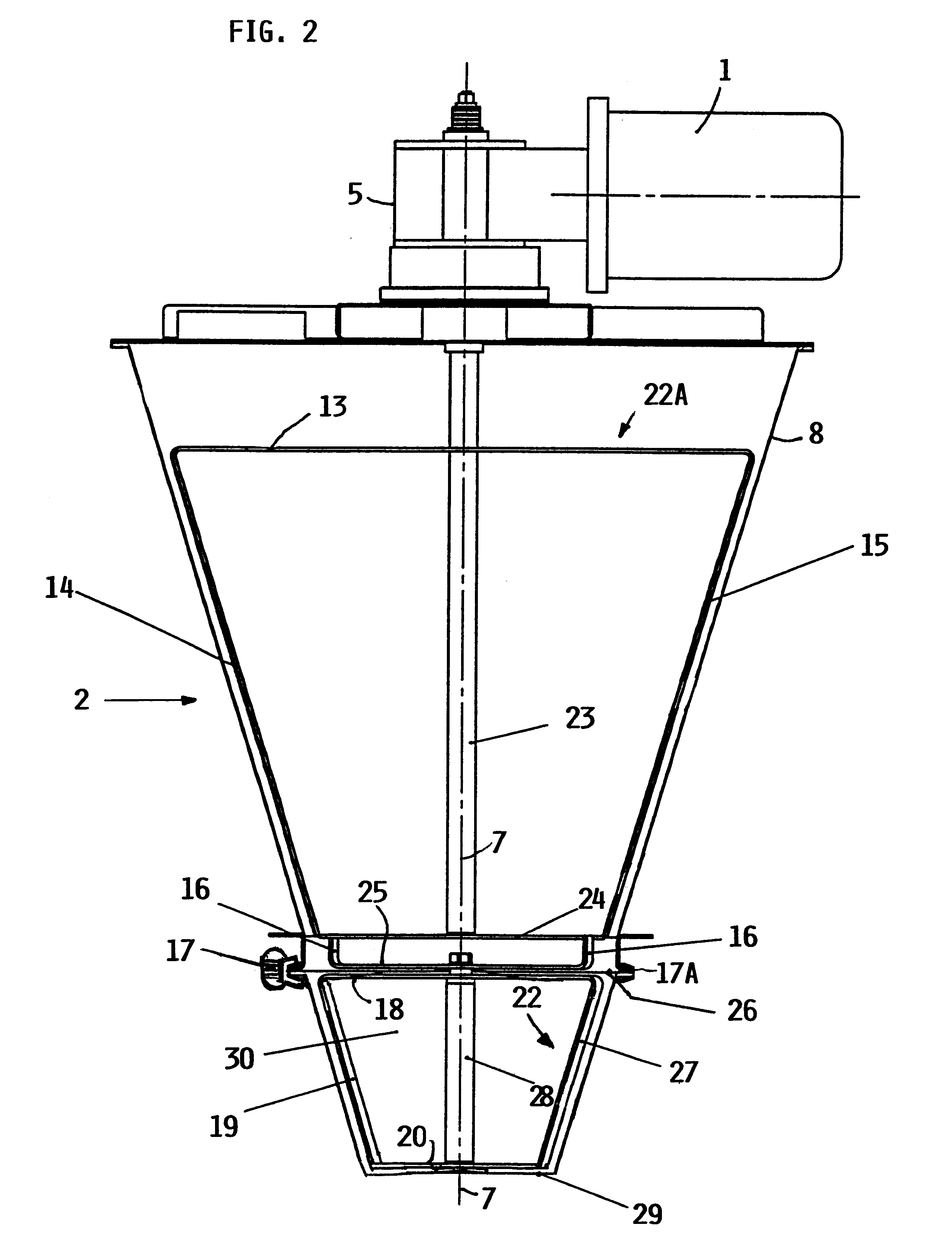
FIG. 1 of the drawings shows a bulk material dosing device 2 having at least two separate container sections or parts including an upper container part 8 and a lower container part 30 for containing bulk material. Further, the dosing device 2 includes a vertical stirring mechanism with a stirring drive 1, and a discharge device 12. The vertical stirring mechanism includes a first vertical stirring section 22 rotatably mounted in the lower container part 30 which is removable laterally in a horizontal direction. The vertical stirring mechanism further includes a second vertical stirring section 22A rotatable mounted in the upper container part 8. The two stirring sections 22 and 22A are coupled to each other in a force-transmitting but releasable manner and the lower stirring section 22 is removable relative to the upper stirring section 22A as will be described in more detail below.

The upper part 8 of the bulk material container is constructed as a supply container 8 which, particul...


PUM


Abstract

The invention relates to a dosing device containing a supply container (8), a dosing container (30) and a discharge device (12). A separate vertical stirring section (22, 22A) is provided in each container, namely the supply container (8) and the dosing container (30). The vertical stirring section 22A located in the supply container (8) is provided with a drive unit (1) which is also used to drive the lower stirrring section (22) of the dosing container (30). The dosing container (30) can be removed horizontally, sideways. The two stirring sections (22) and (22A) have coupling elements (16, 25) with which they are detachably or releasably interconnected. A coupling arm (25) is provided to this purpose with driving pins (16) which engage in the rotating area of the driven upper stirring section (22A) so that the two stirring sections can be coupled and one stirring section can drive the other stirring section.

Description

The invention relates to a dosing device for bulk materials, particularly hard to flow and sticking bulk materials that tend to form bridges in a supply container.BACKGROUND INFORMATIONDosing devices are used in industrial or commercial application processes in which predetermined quantities of bulk materials are, per unit of time, discharged, or are added, or are weighed. Thereby, the bulk materials are withdrawn from a supply container with the aid of discharge devices or conveyor devices and supplied to the scheduled processes.The conveyor devices are arranged, as a rule, below the supply container so that the bulk materials mostly reach the conveyor device under the influence of gravity. Thereby, problems may occur during the continuous feeding from the supply container into the conveyor, particularly in connection with bulk materials that hardly flow, stick together and form bridges. Therefore, it is frequently necessary that the dosing devices are equipped with stirring mechan...

Claims


Application Information

Patent Timeline
Patent Type & Authority Patents(United States)
IPC IPC(8): B65D88/68B65D88/00G01G13/00B65D90/48B65G65/46G01G13/20
CPCB65D88/68
Inventor AHLMER, PETERHEINRICI, HARALD
Owner SCHENCK PROCESS GMBH
Why Eureka
Try Eureka