Antero-postero-stabilized knee prosthesis

a prosthesis and postero-stabilization technology, applied in the field of anteropostero-stabilized knee prosthesis, can solve problems such as not being able to maintain

Inactive Publication Date: 2004-03-02
MERCK BIOMATERIAL FRANCE
View PDF14 Cites 84 Cited by
  • Summary
  • Abstract
  • Description
  • Claims
  • Application Information

AI Technical Summary

Problems solved by technology

However, with the hindsight now available to practitioners, it can be considered that the prostheses that are presently proposed, and more particularly those of the free type, do not make it possible to maintain antero-posterior stabilization, nor to maintain the ...

Method used


Image

  • Antero-postero-stabilized knee prosthesis
  • Antero-postero-stabilized knee prosthesis
  • Antero-postero-stabilized knee prosthesis

Examples


Embodiment Construction

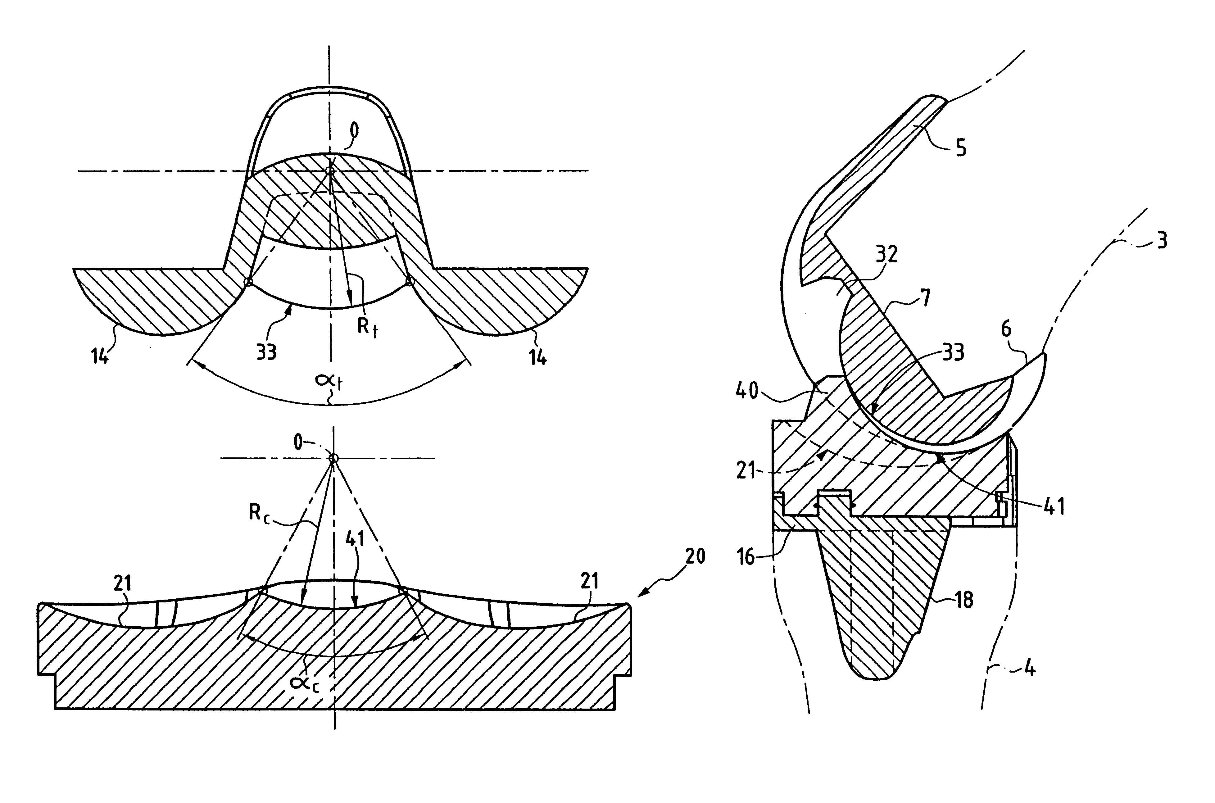
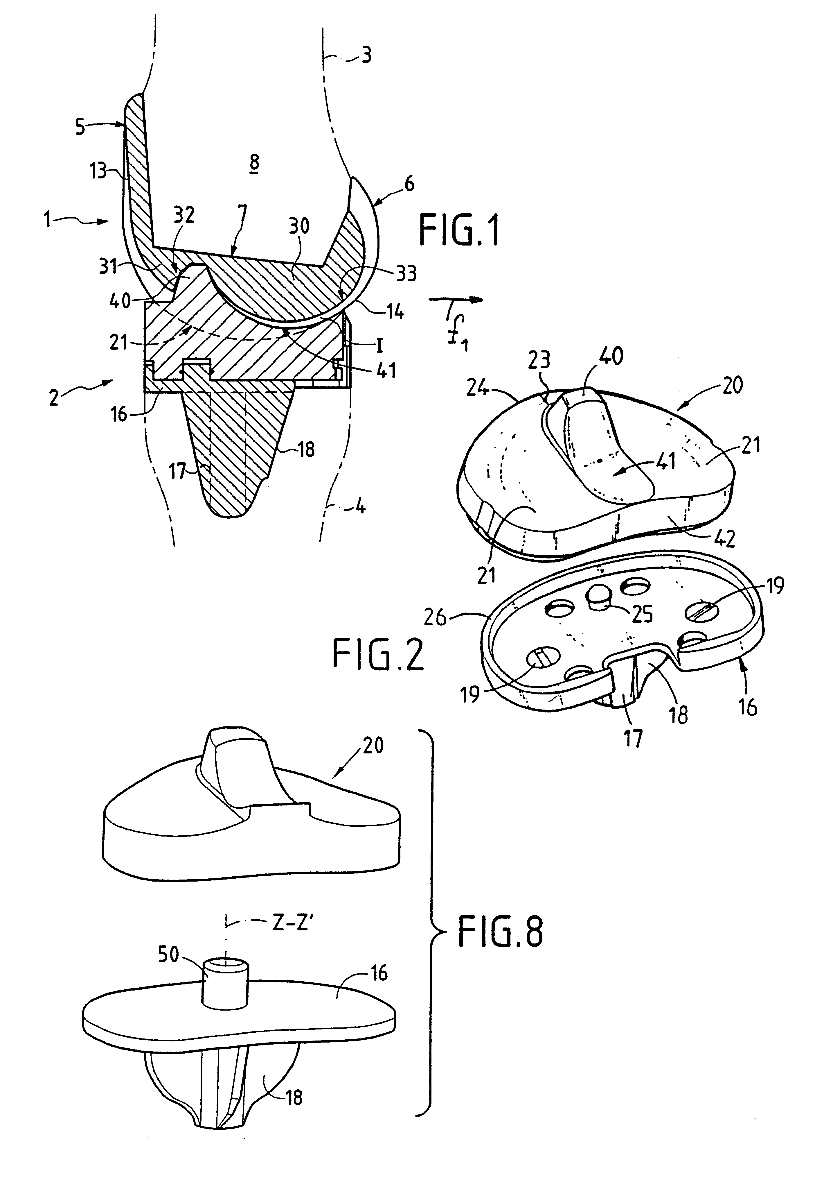
FIG. 1 shows the prosthesis of the invention constituted by a femur prosthetic element 1 and by a tibia prosthetic element 2 for fitting respectively on the bottom epiphysis of the femur 3 and on the top epiphysis of the tibia 4, after resection of the bone.

The femur element 1, which can be made of any suitable material known to the person skilled in the art, is substantially U-shaped in a sagittal plane, comprising a front or anterior portion or branch 5, a rear or posterior portion or branch 6 that is generally shorter than the branch 5, and a core 7 linking the branches together.

The inside surface defined by the femur element defines a kind of polygonal housing 8 for receiving the epiphysis 3 that has previously been subjected to complementary resection.

The femur element is shaped so that the outside surface of its large branch 5 presents a patellar surface 13 defining in conventional manner a trochlea suitable for co-operating with the natural protuberance or with an artificial ...


PUM


Abstract

A prosthesis, such as a knee prosthesis, for the lower limb including a femur prosthetic element having a block presenting a lug running into the trochlea and adjacent to a notch from which a convex bearing surface extends, and a tibia prosthetic element having an insert with a sagittally oriented elevation defining a projection for antero-postero stabilization engaged in the notch when the prosthesis is in the extended position and which runs into a concave sliding ramp that extends to the rear edge of the insert.

Description

The present invention relates to joint prostheses, and more particularly it relates to the field of knee prostheses.The term "knee prosthesis" applies to artificial joint systems intended to replace the natural joint constituted by the conformation of the bottom epiphysis of the femur, by the conformation of the complementary top epiphysis of the tibia, and also by the femoro-patellar element.In the prior art, a large number of proposals have been made that apply to the above technical field.Total prostheses have thus been proposed that are said to be "linked" in that they make use of two complementary parts which are united by a physical hinge system, such as at least one pin, constituting the artificial pivot system enabling the knee to bend in a direction that is perpendicular to the sagittal or antero-posterior plane.Prostheses have also been proposed that are said to be "free" which are constituted, unlike the above prostheses, on the basis of two elements for fitting respectiv...

Claims


Application Information

Patent Timeline
IPC IPC(8): A61F2/38
CPCA61F2/3886
Inventor AUGOYARDBASCOULERGUE, GERARDBASSO, MAURICEBERTOCCHI, RENECHARRET, PHILIPPECOURCELLES, PHILIPPEDEBIESSE, JEAN-LOUISDUPRE LA TOUR, LAURENTEYRAUD, GUYFAYARD, JEAN-PHILIPPEHULIN, PAUL-HENRILECUIRE, FRANCOISMELERE, GILLESMILLON, JOSEPHPASSOT, JEAN-PAULPEYROT, JACQUESRELAVE, MARCDE WITTE, GERARDVERNIZEAU, MICHEL
Owner MERCK BIOMATERIAL FRANCE
Why Eureka
Try Eureka