Telescopic drilling method

a telescopic and drilling method technology, applied in the direction of drilling pipes, drilling holes/well accessories, cutting machines, etc., can solve the problems of casing fracture, special machinery and drilling equipment, and often far water layer

Inactive Publication Date: 2004-03-09
SENSENIG FLOYD R
View PDF4 Cites 94 Cited by
  • Summary
  • Abstract
  • Description
  • Claims
  • Application Information

AI Technical Summary

Problems solved by technology

In addition, the water layer often is far underground and requires special machinery and drilling equipment to reach.
However, the drilling operation creates stress on the casings and weld joints and may cause these casings to fracture.
Such drilling impact and vibration stress is sustained by the rigid one-piece drill casing and its weld joints, causing cracks and fractures, which typically require the hole or bore to be cleared and the drilling process recommenced only after time and material expenditures.
Further, the present drilling methods are slow, as the drill is required to pull the entire casing length along with it as it penetrates further into the earth.
This process is further slowed since the casing being pulled by the drill may be ex

Method used


Image

  • Telescopic drilling method
  • Telescopic drilling method
  • Telescopic drilling method

Examples


Embodiment Construction

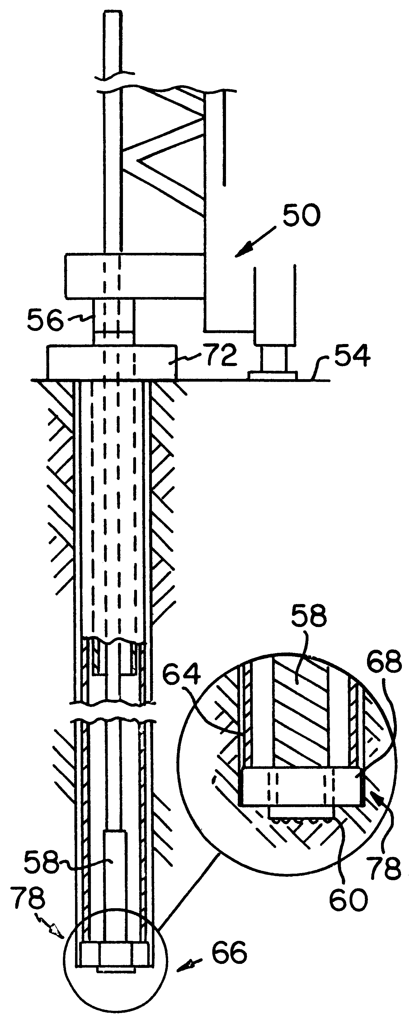
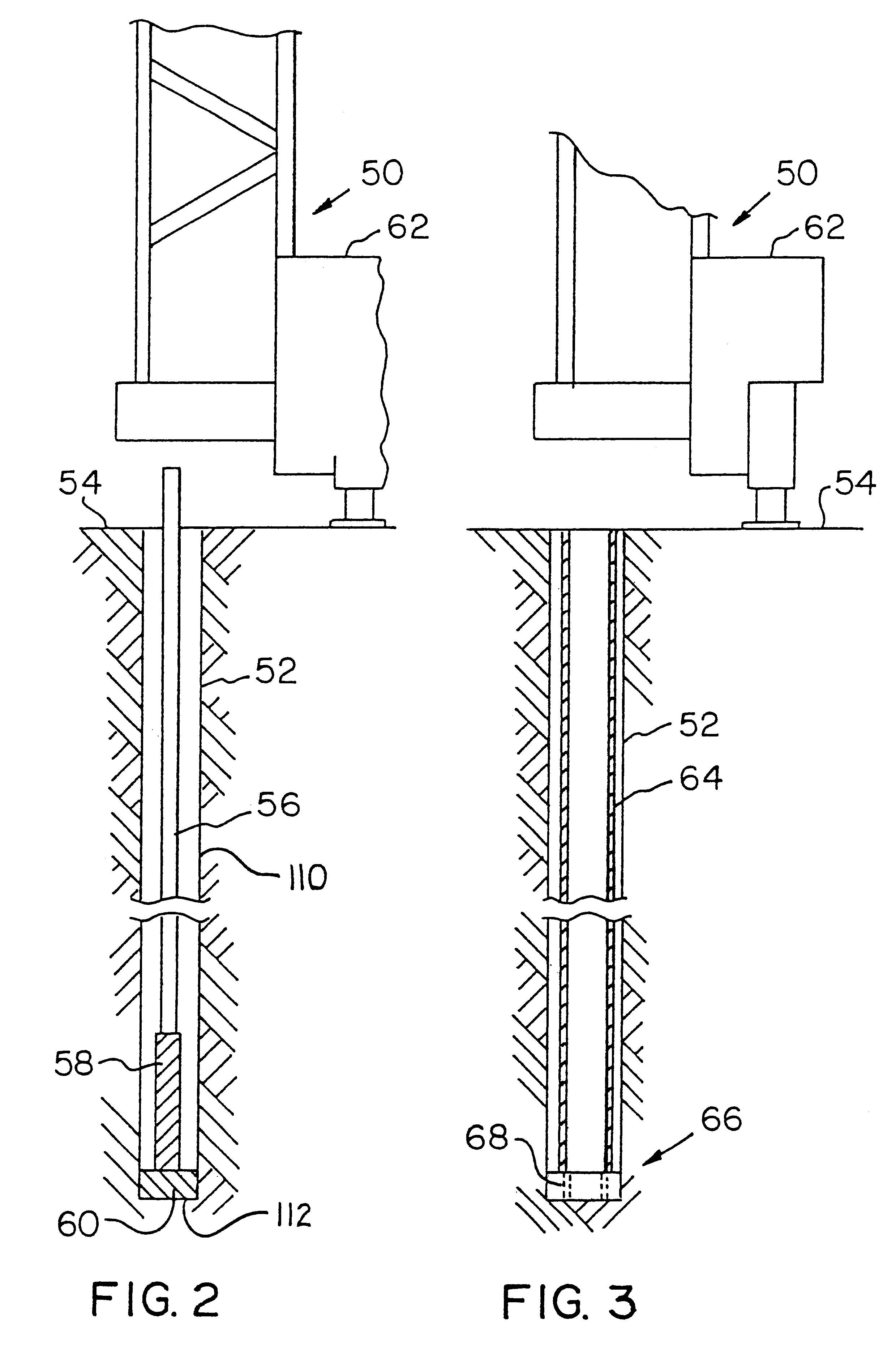
In a specific example of the telescopic drilling method of the present invention, the outer bore 52 has a ten inch diameter, and an initial depth of twenty-five feet. The drill bit is a ten and one-eigth inch diameter bit. The outer conduit 64, with the ring drill bit 68 attached, has a length of twenty-five feet four inches. The ring drill bit 68 has a seven and one-half inch diameter.

The first inner conduit 70, second inner conduit 86 and, therefore, the extended inner conduit 92, have a six and five-eighths inch diameter. As the outer bore 52 deepens to a depth of about forty feet four inches, the outer conduit 64 overlaps the first inner conduit 70 by at least four feet. This ensures that the first inner conduit 70 does not exit and misalign with the outer conduit 64. The clamping mechanism 72 holds the second inner conduit first end 88 and / or the extended inner conduit first end 94 approximately one foot above the surface 54. After the first inner conduit 70 and second inner co...


PUM


Abstract

A telescopic drilling method includes the steps of drilling an outer bore through a surface, inserting a hollow outer conduit into the outer bore, and at least partially inserting a first hollow inner conduit through the outer conduit. Next, the method includes the steps of preventing the first inner conduit from moving longitudinal with respect to the outer conduit engaging a rotatable inner drill bit with a ring drill bit and further drilling the outer bore using a unitary drill bit head to a successive depth. The inner drill bit is disengaged from the ring drill bit and a second end of a successive hollow inner conduit is attached to a first end of a preceding one, and the preceding inner conduit is unclamped.

Description

1. Field of the InventionThe present invention relates generally to drilling methods, and, in particular, to telescopic drilling methods for use in connection with overburden drilling operations.2. Description of Related ArtIn order to collect and transfer water, wells are used and created by drilling a well hole or bore into the ground to an aquifer or water layer. As these bores are being drilled, often an overburden layer or rock layer is encountered and must be breached prior to reaching the water layer. In addition, the water layer often is far underground and requires special machinery and drilling equipment to reach.Prior art drilling systems use long conduits, referred to as casings, welded together and gradually moved down the bore as it is drilled. However, the drilling operation creates stress on the casings and weld joints and may cause these casings to fracture. Such drilling impact and vibration stress is sustained by the rigid one-piece drill casing and its weld joint...

Claims


Application Information

Patent Timeline
IPC IPC(8): E21B17/07E21B17/02E21B7/00E21B7/20
CPCE21B7/00E21B7/208E21B17/07
Inventor SENSENIG, FLOYD R.
Owner SENSENIG FLOYD R
Why Eureka
Try Eureka