Multi-cylinder compression pump

a multi-cylinder, compression pump technology, applied in the direction of positive displacement pump components, liquid fuel engine components, etc., can solve the problems of air compression, not satisfactory pump type,

Inactive Publication Date: 2004-03-09
FX AIRGUNS AB
View PDF14 Cites 18 Cited by
  • Summary
  • Abstract
  • Description
  • Claims
  • Application Information

AI Technical Summary

Problems solved by technology

However, when sufficiently high pressures are required, for example in the magnitude of 200 bars, pumps of the kind defined above are not satisfactory either.
Since the goods in the first cylinder occupies some of the space between the second and third chambers, the total cross-sectional area of these chambers is inferior to the cross-sectional area of the fourth chamber, and consequently compression of the air takes place.

Method used


Image

  • Multi-cylinder compression pump
  • Multi-cylinder compression pump
  • Multi-cylinder compression pump

Examples


Embodiment Construction

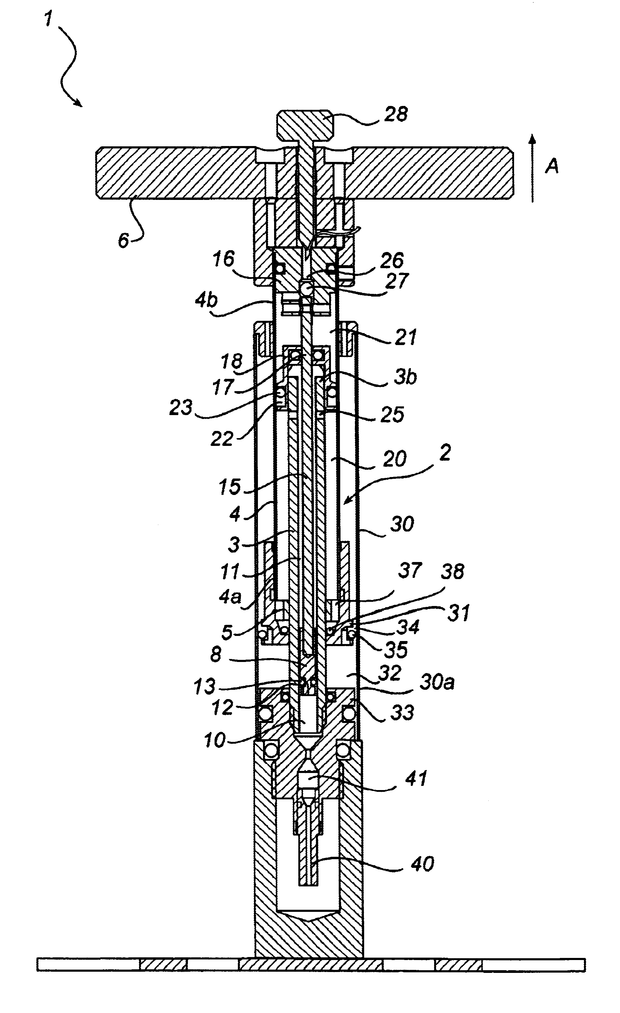
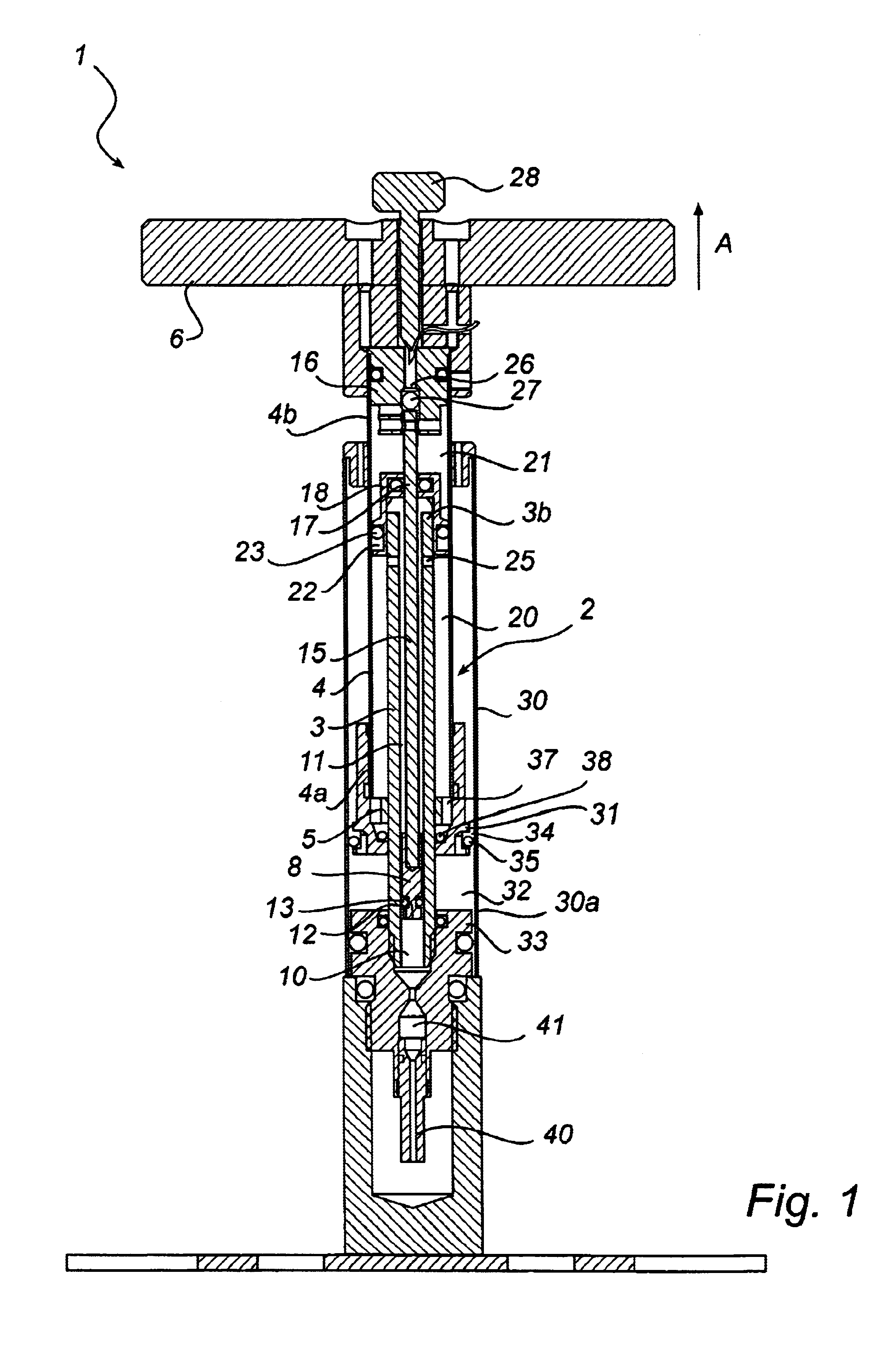
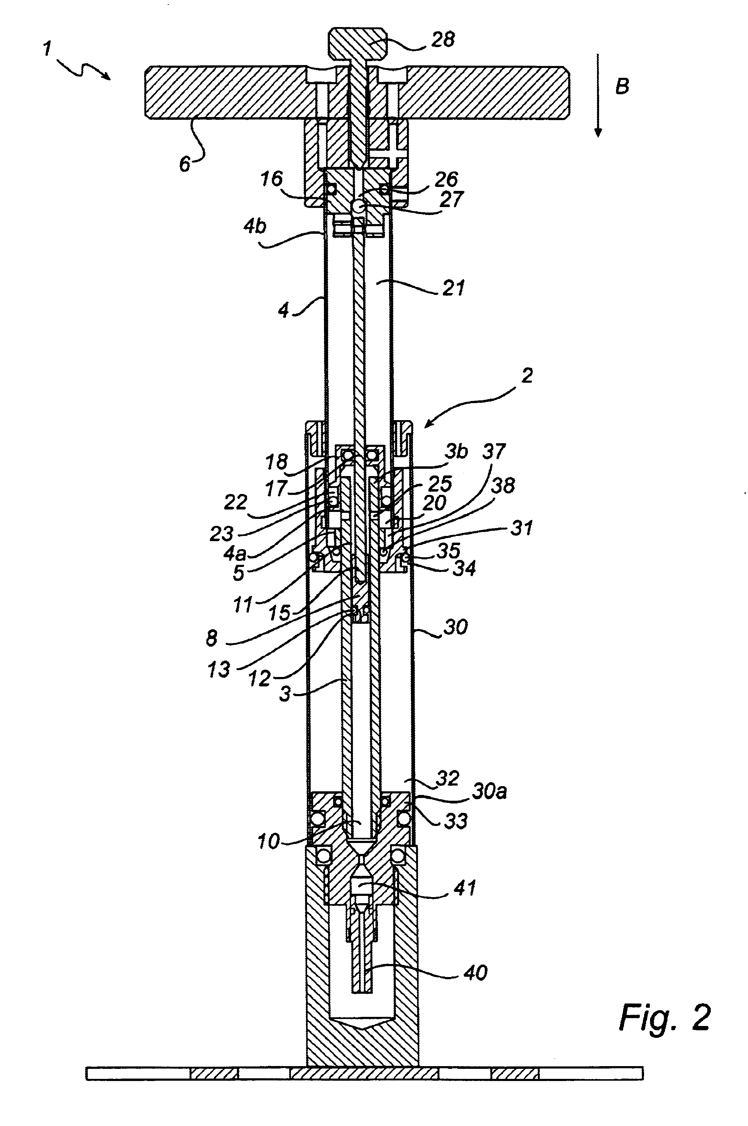
The pump illustrated in FIGS. 1-2 comprises a pump housing 2 consisting of a first, stationary cylinder 3 and a second, movable cylinder 4 surrounding the first cylinder and arranged to move to and from in the lengthwise direction of the first cylinder. The lower end 4a of the movable cylinder 4 is formed with an annular end wall 5 in tightly sealed contact with the external face of the first cylinder 3. At the upper end 4b of the second cylinder 4 an operating handle 6 is provided, making it more convenient for the user to effect pumping movements of the cylinders 3, 4 relative to one another.

The stationary cylinder 3 houses a piston 8 dividing the cylinder 3 into a first lower chamber 10 located ahead of the piston and a second upper chamber 11 located behind the piston. The chambers 10 and 11 communicate via a through-passage channel 12 formed in the piston 8 and formed with a through-passage valve 13, such as an O-ring allowing air passage only from the upper chamber 11 to the l...


PUM


Abstract

The invention concerns a pump for compression of gases, such as air, of the type comprising a first cylinder and a second cylinder, a piston dividing said first cylinder into a first chamber located ahead of the piston and a second chamber located behind the piston, the piston and the second cylinder arranged to be displaced jointly relative to the first cylinder. A third chamber is formed between end walls of the cylinders and communicates with said second chamber via at least one opening formed in the jacket wall of the first cylinder. The pump is characterized by an inlet provided in the second end of the second cylinder in order to allow passage of air into a fourth chamber formed between the second end of the second cylinder and the end wall of the first cylinder, said fourth chamber communicating with said third chamber via a through-passage channel, wherein a valve is provided, formed in the end wall of the first cylinder.

Description

The present invention relates to an improved pump for compression of gases, such as air, comprising a first, stationary cylinder, wherein a piston is arranged for movement in the longitudinal direction of said cylinder so as to divide the latter into a first chamber located ahead of the piston, and a second chamber located behind the piston, a piston rod securely joining said piston to a second movable cylinder arranged externally of the first cylinder so as to ensure co-ordination of the movements of said piston and said second cylinder. The open end of said second cylinder is sealed against the external face of the first cylinder and the open end of the first cylinder is sealed against the internal wall of the second cylinder, whereby a third chamber is formed between the seals.TECHNICAL BACKGROUNDPumps of the above kind are known from SE 463 732 and could be regarded as a two-step pump because the compression of air takes place in two steps, viz. both when the cylinders pushed to...

Claims


Application Information

Patent Timeline
Patent Type & Authority Patents(United States)
IPC IPC(8): F04B33/00F04B5/00F04B5/02
CPCF04B5/02F04B33/005
Inventor AXELSSON, FREDRIK
Owner FX AIRGUNS AB
Why Eureka
Try Eureka