
Method of controlling a closed loop performing a rankine cycle and loop using same

a closed loop and rankine cycle technology, applied in the direction of machines/engines, vehicular safety arrangements, pedestrian/occupant safety arrangements, etc., can solve the problems of system controlling the rankine cycle loop becoming inoperative, and fluid may also appear intrinsically dangerous

Inactive Publication Date: 2013-05-02
INST FR DU PETROLE
View PDF4 Cites 10 Cited by
  • Summary
  • Abstract
  • Description
  • Claims
  • Application Information

AI Technical Summary

Benefits of technology

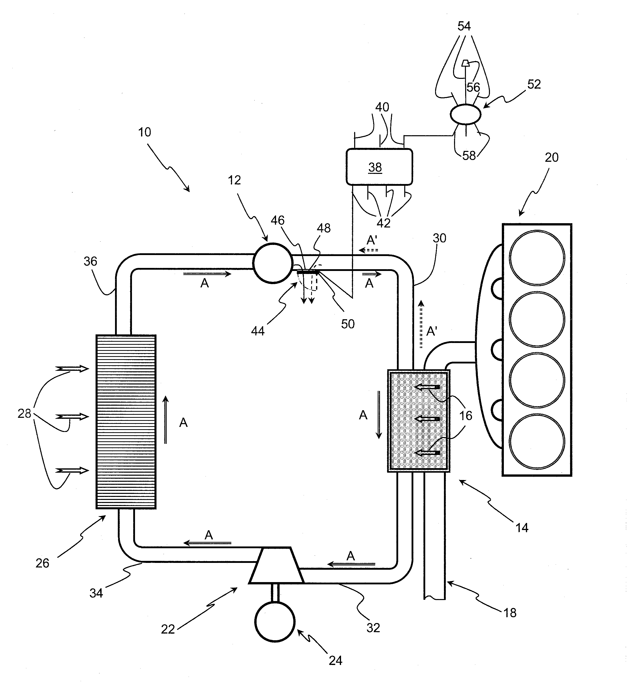
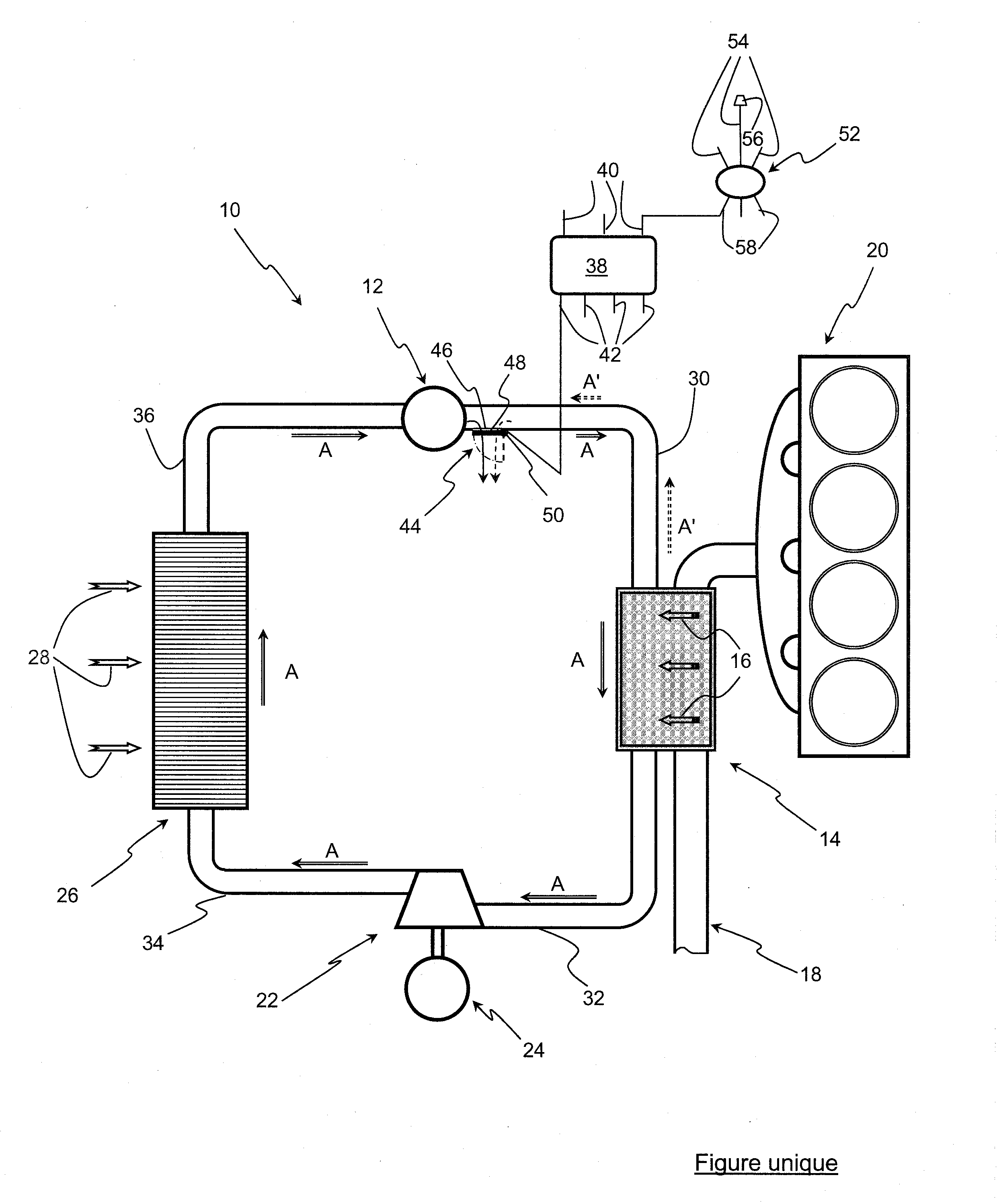
The present invention is related to a method and device for controlling a closed loop performing a Rankine cycle for a motor vehicle. The method involves detecting a vehicle accident and opening the loop with ambient air to cool the working fluid. This helps to prevent damage to the system and ensures the vehicle's safety during emergency situations. The device includes an opening located on at least one element of the loop and throttling means controlling this opening. The opening can be provided on at least one of the exchangers and / or circulation lines. The throttling means can include a valve switching between an extreme position closing the opening and another extreme position of clearing the opening. The hot source can come from the exhaust gas of an internal-combustion engine.

Problems solved by technology

Furthermore, when using certain working fluids, this fluid may also appear to be intrinsically dangerous, notably flammable.
Thus, in case of an abnormal situation of the vehicle, an accident for example, the system controlling the Rankine cycle loop can become inoperative, either as a result of a malfunction of the control system itself or of a malfunction of the sensors or the driving actuators.
These levels can lead to a sudden break in one or more elements of the loop (fluid circulation line, exchanger, etc.), thus causing yet another accident.

Method used


Image

  • Method of controlling a closed loop performing a rankine cycle and loop using same
  • Method of controlling a closed loop performing a rankine cycle and loop using same

Examples


Embodiment Construction

[0026]The present description relates more particularly to a closed loop with a phase change fluid, but any other Rankine cycle loops, such as those referred to as supercritical fluid loops (with CO2 for example), can be used.

[0027]In FIG. 1, Rankine cycle closed loop 10 comprises a circulation and compression means 12 for a working fluid, water here, circulating clockwise (arrows A) in this loop. This means, referred to as pump in the rest of the description, allows to compress this water between the pump inlet and its outlet where this water, still in liquid form, is at high pressure.

[0028]This pump is advantageously driven in rotation by any known means such as an electric motor (not shown).

[0029]This loop also comprises a heat exchanger 14, referred to as evaporator, traversed by the compressed water coming from the pump that flows out of this evaporator in form of hot compressed vapour.

[0030]This evaporator is swept by a hot source 16 coming from the exhaust gas circulating in ...


PUM


Abstract

The present invention relates to a method of controlling a closed loop (10) performing a Rankine cycle for a motor vehicle, said loop comprising a circulation and compression pump (12) for a working fluid, a heat exchanger (14) swept by a hot source (16) for heating said working fluid, expansion means (22) for expanding the hot fluid and a cooling exchanger (26) swept by a cooling fluid (28) for cooling this working fluid.According to the invention, the method consists, after detecting a vehicle accident situation, in communicating the inside of the loop with the ambient air.

Description

FIELD OF THE INVENTION[0001]The present invention relates to a method of controlling a closed loop performing a Rankine cycle and to a loop using same.[0002]As it is well known, a Rankine cycle is a thermodynamic cycle through which heat coming from an external heat source is transmitted to a closed loop that contains a fluid.BACKGROUND OF THE INVENTION[0003]There are many types of Rankine cycle loops and more particularly those involving a (liquid / vapour) phase change of a working fluid.[0004]This type of cycle generally consists of a stage wherein the working fluid used in liquid form is compressed in an isentropic manner, followed by a stage where this compressed liquid fluid is heated and vaporized on contact with a source of heat.[0005]This vapour is then expanded, in another stage, in an isentropic manner in an expansion machine, then, in a last stage, this expanded vapour is cooled and condensed on contact with a cold source.[0006]To carry out these various stages, the loop c...

Claims


Application Information

Patent Timeline
Patent Type & Authority Applications(United States)
IPC IPC(8): F01K13/02F01K15/00
CPCA45C9/00A45C15/00F01K25/10F01K23/065F01K13/006B60R21/013B60R21/0132
Inventor LEDUC, PIERRE
Owner INST FR DU PETROLE
Learn More