

Steam power circulation and device
A technology of steam power and steam, applied in the direction of steam engine devices, machines/engines, mechanical equipment, etc., can solve problems such as low thermal efficiency, energy crisis, energy waste, etc., and achieve high thermal efficiency
- Summary
- Abstract
- Description
- Claims
- Application Information
AI Technical Summary
Problems solved by technology
Method used
Image

Examples
Embodiment 1
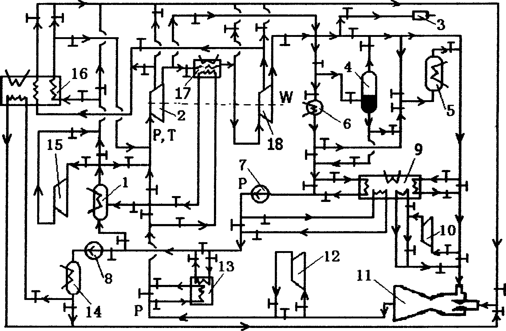
[0021] Embodiment 1: In this embodiment, water vapor is used as the working medium, and the expander (2) adopts a steam turbine (2). The steam turbine (2) and the vapor-liquid separator (4) are evacuated by the vacuum pump (3): the steam generator (1) absorbs heat from the heat source to generate saturated water vapor with a pressure of 4MPa and a temperature of 250°C as the initial state ; After the saturated water vapor expands in the steam turbine (2) and does work to 2kPa and 17.5°C, it becomes exhausted gas containing saturated liquid, and the exhausted gas is divided into two parts: saturated liquid and saturated steam through the vapor-liquid separator (4); wherein the saturated steam After the ejector (11), the compressor (12) and the heat exchanger (13) restore the original state, and the saturated liquid is compressed by the compressed water pump (7) to increase to the initial pressure, and then through the heat exchanger (13) for heat exchange and The initial state ...
Embodiment 2
[0053] Embodiment 2: In this embodiment, water vapor is used as the working medium, the expander (2) adopts the steam turbine (2), and the heat exchange process of the heat pump is introduced on the basis of the embodiment 1. The steam turbine (2) and the vapor-liquid separator (4) are evacuated by the vacuum pump (3); the steam generator (1) absorbs heat from the heat source to generate saturated water vapor with a pressure of 4MPa and a temperature of 250°C as the initial state; After the saturated steam expands in the steam turbine (2) and does work at 2kPa at 17.5°C, it becomes exhaust gas containing saturated liquid, and the exhaust gas passes through the vapor-liquid separator (4) and is divided into two parts: saturated liquid and saturated steam; the saturated steam first Exchange heat with the heat pump (9) to raise the temperature to 80°C, and then restore the initial state through the ejector (11), compressor (12) and heat exchanger (13); the saturated liquid first e...
Embodiment 3
[0083]Embodiment 3: In this embodiment, water vapor is used as the working medium, and the expander (2) adopts a steam turbine (2). The steam turbine (2), evaporator (5), and vapor-liquid separator (4) are evacuated by the vacuum pump (3); the steam generator (1) absorbs heat from the heat source to generate a vacuum chamber with a pressure of 4MPa and a temperature of 250°C. Saturated water vapor is taken as the initial state; after the saturated water vapor expands in the steam turbine (2) and does work to 2kPa and 17.5°C, it becomes exhaust gas containing saturated liquid, and the exhaust gas is divided into saturated liquid and saturated steam through the vapor-liquid separator (4) Two parts; the saturated liquid evaporates into saturated steam at 2kPa and 17.5°C after absorbing heat from the cold source in the evaporator (5); the saturated steam returns to its original state through the ejector (11), and part of the initial saturated steam passes through the compressor (1...
PUM
 Abstract
Description
Claims
Application Information