Creeping soft tube pump

A hose pump, hose technology, used in pumps, machines/engines, pumps with flexible working elements, etc., can solve problems such as restoring force attenuation

Inactive Publication Date: 2004-02-11
B BRAUN MELSUNGEN AG
View PDF1 Cites 10 Cited by
  • Summary
  • Abstract
  • Description
  • Claims
  • Application Information

AI Technical Summary

Problems solved by technology

This can lead to premature decay of the restoring force

Method used


Image

  • Creeping soft tube pump
  • Creeping soft tube pump
  • Creeping soft tube pump

Examples


Embodiment Construction

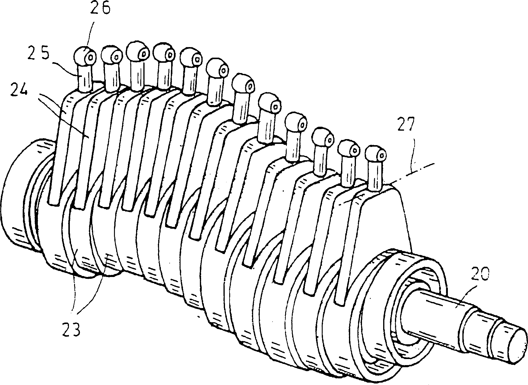
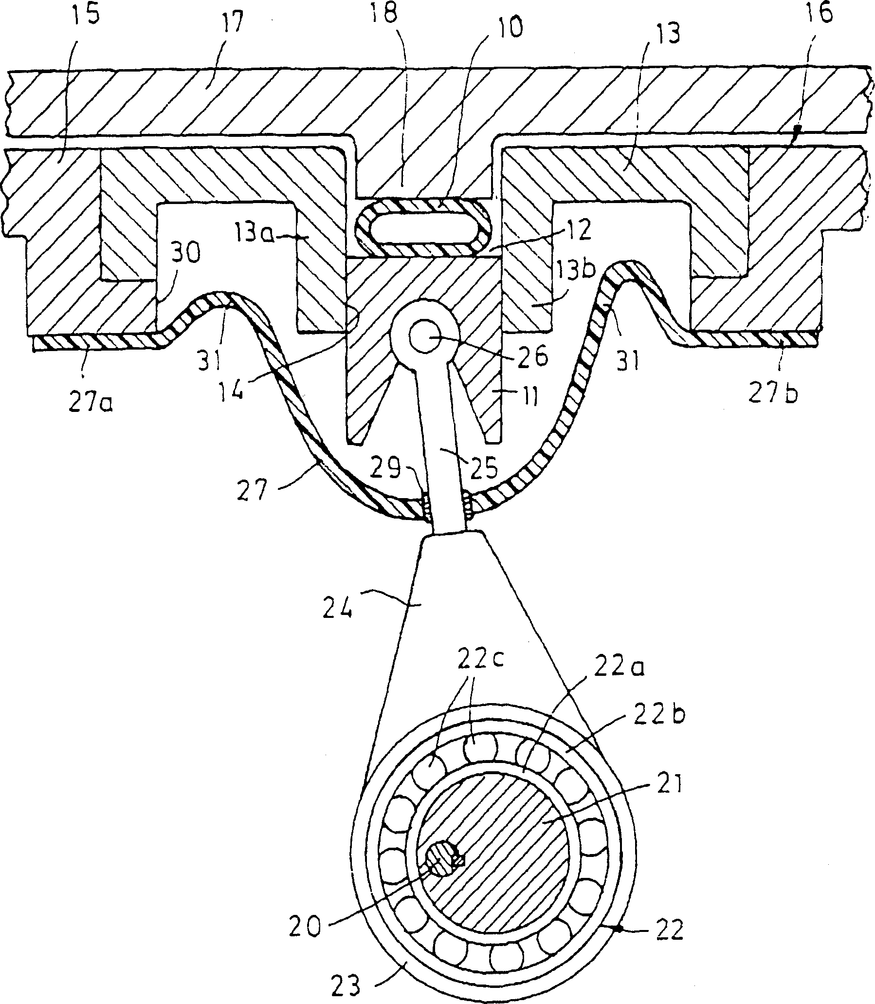
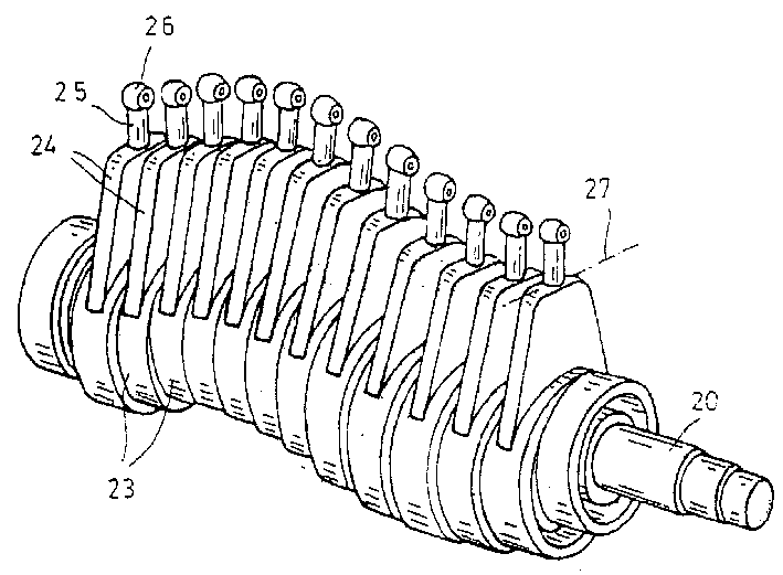
[0013] The hose pump shown in the figure comprises a pump hose 10 in which the liquid to be pumped is carried. This hose is continuously, periodically compressed and released by the fingers 11 of a plurality of pumps, as described in European Patent 0 214 443 .

[0014] The pump hose 10 is accommodated in an accommodation passage 12 formed in the guide plate 13 . The guide plate 13 has parallel walls 13a, 13b laterally forming the receiving channel 12 . The receiving channel 12 is connected to a plurality of guide grooves 14, in each of which a finger 11 of a pump is guided transversely in the direction of the hose. The guide plate 13 is attached to the front wall 15 of the pump housing 16 . The pump housing has a dour attached to its front, which forms a thrust bearing 17 for supporting the pump hose 10 . The thrust bearing 17 has a projection 18 protruding into the receiving channel 12 .

[0015] There are about twelve pump fingers 11 in total, which are driven sinusoida...


PUM


Abstract

The wriggling hose pump has an eccentric driving part furnished with a plurality of eccentric discs 21 to be fixed on a shaft 20. Each of the eccentric discs 21 drives a crank driving part 24 with a connecting rod 25. A pump finger 11 to compress a pump hose 10 is supported on an end part of the connecting rod 25. A seal diaphragm 27 to prevent intrusion of liquid to the inside of a housing 16 is arranged between the eccentric driving part and the pump hose 10. The seal diaphragm 27 has a side-way bent 31 so that it does not have substantial force work on the crank driving part 24.

Description

technical field [0001] The present invention relates to a peristaltic hose pump having a shaft comprising a plurality of eccentric discs, each bearing a bearing and thereby moving the fingers of the pump laterally towards the pump hose; and having a Sealing diaphragm between shaft and pump hose. Background technique [0002] In the medical field, peristaltic hose pumps are frequently used as syringe or infusion pumps for the transfer of liquid substances. As is known in linear hose pumps, a plurality of pump fingers successively and cyclically press a straight pump hose against a support surface so that the liquid in the pump hose moves in the direction of delivery. European patent 0 214 443 A1 describes a peristaltic linear hose pump with a plurality of eccentric discs fastened to a shaft. Each eccentric disc has a ball bearing and acts on a linearly movable pump finger. All pump fingers are covered by a sealing diaphragm that forms a tight separation between the drive m...

Claims


Application Information

Patent Timeline
Patent Type & Authority Applications(China)
IPC IPC(8): F04B43/12F04B43/08
CPCF04B43/082
Inventor 迪特尔·赫维希赖因哈德·克努特
Owner B BRAUN MELSUNGEN AG
Why Eureka
Try Eureka