Feedback control system, control method, magnetic disk unit and method of controlling magnetic disk unit

a control system and magnetic disk technology, applied in the direction of maintaining head carrier alignment, electric controllers, instruments, etc., can solve the problems of increasing sampling frequency, difficult to set the high-order resonance mode of the actuator in a high-frequency band, and difficult to provide the present control method

Inactive Publication Date: 2004-03-09
KK TOSHIBA
View PDF7 Cites 11 Cited by
  • Summary
  • Abstract
  • Description
  • Claims
  • Application Information

AI Technical Summary

Benefits of technology

Generally, a digital control system includes necessarily a phase lag due to digitization and an operation time lag. Particularly, digitization causes a great phase lag and a phase lag starts developing in a frequency band far lower than a Nyquist frequency. The phase lag is a significant factor that restricts the control performance of digital control. Generally, a phase lead compensating device included in a feedback control system of a digital control system is used to compensate the phase lag. Gain margin is reduced and hence stability is deteriorated by the strong phase lead compensation by the phase lead compensating device. Therefore, the phase lag cannot be greatly recovered by the phase lead compensating device. Consequently, the control band is limited to a very low frequency band as compared with the sampling frequency; that is, sufficient phase margin and gain margin of an open-loop characteristic can be secured even if the same sampling frequency is used, provided that the phase lag due to digitization can be reduced, so that positioning accuracy can be improved. Accordingly, the present invention pays attention to phase lag due to digitization.
A zero-order sample holder holds a value sampled at sampling time for a sampling period. A zero-order sample holder is a easily realizable piece of hardware and hence the same is employed in many digital controllers. Phase lag due to digitization is caused by the position of the zero point of a transfer function when a zero-order sample holder is used. The phase lag due to digitization can be changed by changing the position of the zero point of the transfer function.
The present invention reduces phase lag due to digitization by using a easily realizable zero-order sample holder. The present invention executes a multirate control that performs an output operation a plurality of times in one sampling period to make the transfer function of an actuator have a zero point at a specified position. Thus, phase lag due to digitization can be reduced by using hardware similar to conventional hardware employing a zero-order sample holder.
As mentioned above, the present invention uses multirate control for feedback control, and determines the position of the zero point of a digitization model optionally, so that a phase lag due to digitization can be recovered greatly and a feedback control system according to the present invention has a phase margin and a gain margin which are greater than those of the conventional feedback control system. At the same time, the excitation of the mechanical resonance point is avoided by setting time allotment and gain for multirate control output.

Problems solved by technology

However, the magnetic disk unit has difficulties in increasing the sampling frequency for many reasons and it is difficult to set the high-order resonance mode of the actuator in a high-frequency band.
Under such circumstances, it is difficult for the present control method to provide the open-loop characteristic of a feedback control system with sufficient phase margin and gain margin.
Thus, it is very difficult to enhance robustness with the variation of the actuator characteristic and to achieve accurate positioning.
Thus, it is very difficult for the conventional digital control system to achieve accurate positioning at a low sampling frequency.
The phase lag is a significant factor that restricts the control performance of digital control.
Gain margin is reduced and hence stability is deteriorated by the strong phase lead compensation by the phase lead compensating device.
Therefore, the phase lag cannot be greatly recovered by the phase lead compensating device.
On the other hand, although a zero-order sample holder can be easily formed, it is not expedient to use a zero-order sample holder from the viewpoint of the ability of a feedback control system.
However, those previously proposed high-order sample holders are difficult to realize and are deemed to be scarcely practically feasible.
Avoidance of the effect of the mechanical resonance point of an actuator is another problem.

Method used


Image

  • Feedback control system, control method, magnetic disk unit and method of controlling magnetic disk unit
  • Feedback control system, control method, magnetic disk unit and method of controlling magnetic disk unit
  • Feedback control system, control method, magnetic disk unit and method of controlling magnetic disk unit

Examples


Embodiment Construction

Embodiment of the present invention will be described hereinafter with reference to the accompanying drawings.

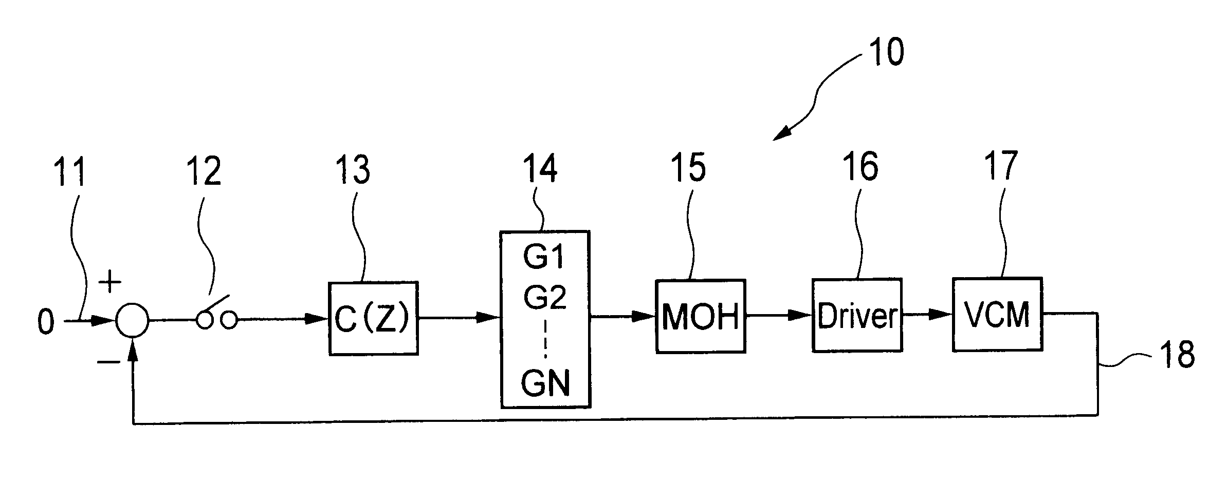
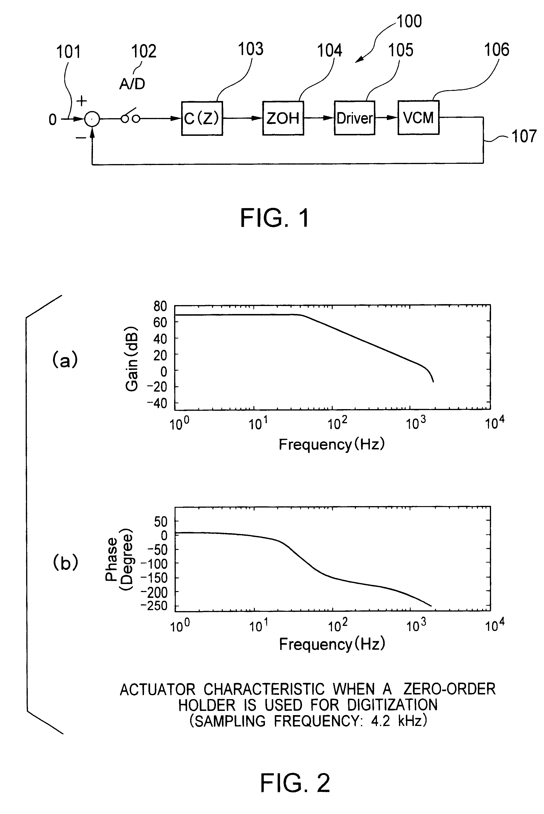
Referring to FIG. 1 showing a conventional feedback control system 100, a positional error, i.e., the difference between a desired value 101 and an output 107 provided by an actuator 106, i.e., a controlled device, is subjected to A / D conversion by an A / D converter 102. A feedback control unit 103 samples a digital positional error provided by the A / D converter 102 at a predetermined sampling period, calculates a control command value every time the digital positional error is sampled. A zero-order sample holder 104 holds the control command value calculated by the feedback control unit 103 for the sampling period and gives the same with a delay corresponding to an operation time through a driver to an actuator 106. Given that the actuator 106 is a simple second-order system, the actuator 106 shows a gain characteristic and a phase characteristic as shown in FIG. 2. In this ...


PUM

PropertyMeasurementUnit
frequencyaaaaaaaaaa
Nyquist frequencyaaaaaaaaaa
frequencyaaaaaaaaaa

Abstract

A feedback control system applicable to a magnetic disk unit is capable of improving the accuracy of positioning at a low sampling frequency. The feedback control system comprises a feedback control unit (13) that samples a differential signal representing a difference between a desired value (11) and an output provided by a controlled device (17) at a sampling frequency and produces a control command value every time the differential signal is sampled, a multigain means (14) that divides one sampling period into a combination of a plurality of time periods (T1 to TN) according to a predetermined time period dividing rule and allots gains to the plurality of time periods, respectively, according to a predetermined gain allotting rule, a multihold means (15) that holds the products of the control command value and the gains allotted by the multigain allotting means as fixed values for the time periods and generates a control waveform, and a driving means (16) that applies the control waveform generated by the multihold means to the controlled device.

Description

1. Field of the InventionThe present invention relates to a feedback control system, a control method, a controller for controlling a magnetic disk unit, and a method of controlling the magnetic disk unit. More particularly, the present invention relates to positioning the magnetic head of a magnetic disk unit.2. Description of the Related ArtGenerally, a digital control system including a microcomputer is employed for positioning the head of a magnetic disk unit.In the digital control system, the microprocessor calculates a command value on the basis of position information about the position of the head of the magnetic disk unit given through an A / D converter to the microprocessor, the calculated command value is given as a control command through a D / A converter to a drive unit for driving a voice coil motor (VCM), i.e., an actuator included in the magnetic disk unit.High-order resonance characteristic with a sampling frequency of the actuator is very important to achieve precisi...

Claims


Application Information

Patent Timeline
Patent Type & Authority Patents(United States)
IPC IPC(8): G11B21/10G11B5/596G05B11/36G11B20/10G05B21/02
CPCG11B5/59627G11B21/10G11B20/10
Inventor TAKAKURA, SHINJI
Owner KK TOSHIBA
Why Eureka
Try Eureka