
Ported subsea wellhead

a technology for subsea wells and wellheads, which is applied in the direction of underwater drilling, drilling machines and methods, borehole/well accessories, etc., can solve the problems of leakage in one of the casing strings, compromising the structural and pressure integrity of the well, and difficulty in monitoring the pressure of the annulus of the production casing in the subsea well

Inactive Publication Date: 2004-03-16
ABB VETCOGRAY
View PDF7 Cites 43 Cited by
  • Summary
  • Abstract
  • Description
  • Claims
  • Application Information

AI Technical Summary

Benefits of technology

"The patent text describes a system for monitoring the pressure in a subsea well. The system includes a subsea wellhead housing with a production casing hanger and an intermediate casing hanger landed in it. The system also includes a tubing hanger assembly for supporting tubing in the well. The tubing hanger assembly has a flow passage for communication between the production casing and the tubing. The system allows for monitoring the pressure in the annulus between the production casing and the next larger string of casing, which is important for maintaining the structural and pressure integrity of the well. The system can be used in subsea wells with a tree assembly and can provide early detection of leaks in the casing strings."

Problems solved by technology

If pressure within this annulus increases, it would indicate that a leak exists in one of the strings of casing.
Regardless of where the leak is coming from, pressure build up in the annulus between the production casing and the next larger string of casing could collapse a portion of the production casing, compromising the structural and pressure integrity of the well.
Monitoring production casing annulus pressure in a subsea well is more difficult because of lack of access to the wellhead housing below the production casing hanger packoff.
However, most subsea wells do not have any ability to monitor casing annulus pressure.

Method used


Image

  • Ported subsea wellhead
  • Ported subsea wellhead
  • Ported subsea wellhead

Examples


second embodiment

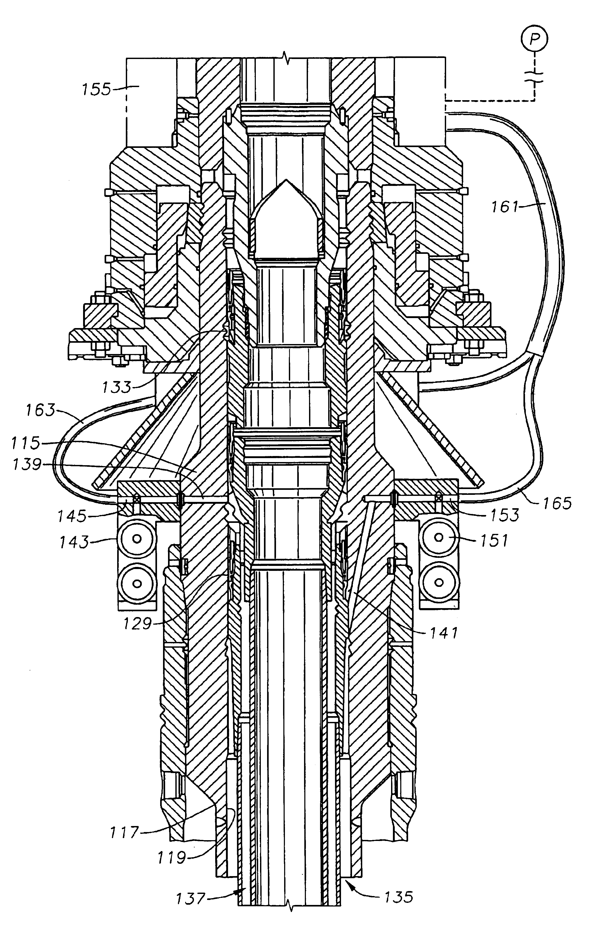
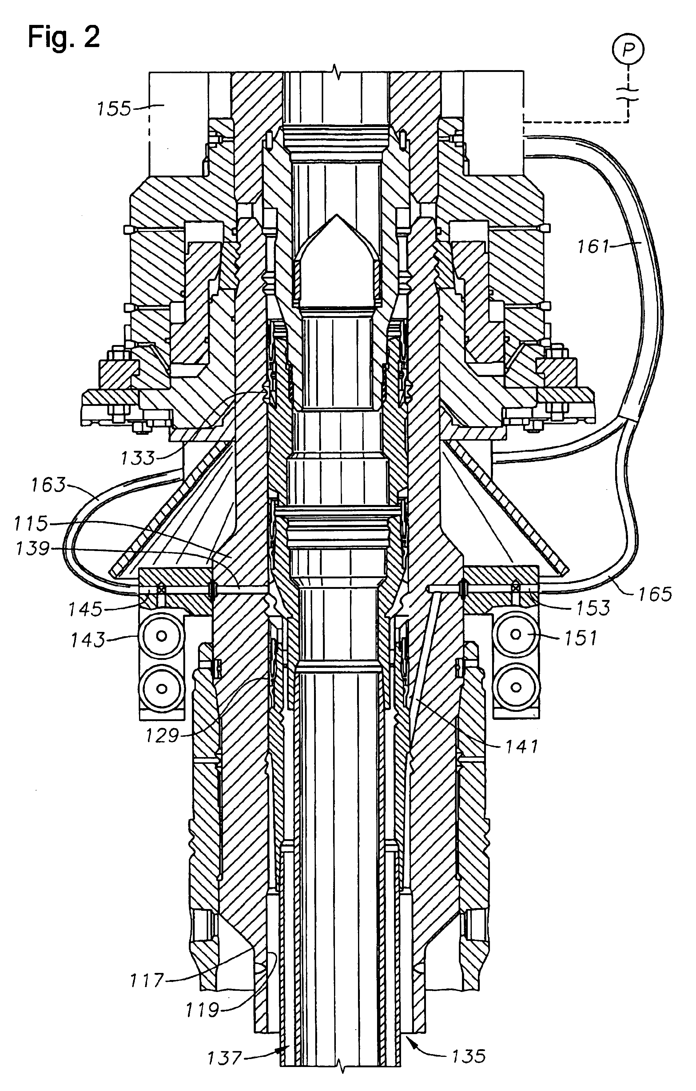
FIG. 2 shows the well assembly. Referring to FIG. 2, a production casing annulus passageway 139 extends laterally through high pressure wellhead housing 115 from interior surface 119 towards exterior surface 117. Production passageway 139 begins above intermediate casing hanger packoff 129 and below production hanger casing packoff 133. Production passageway 139 connects with production casing valve 143. Annulus valve 143 prevents pressure communication of production casing annulus 137 while closed. Production passageway 139 continues after annulus valve 143 to a production passageway outlet 145 located on exterior surface 117 of high pressure wellhead housing 115.

An intermediate casing annulus passageway 141 extends laterally through high pressure wellhead housing 115 from interior surface 119 towards exterior surface 117. Intermediate passageway 141 begins below intermediate casing hanger packoff 129. Intermediate passageway 141 connects with intermediate casing valve 151. Interme...

third embodiment

FIGS. 3 and 4 show the well assembly. Referring to FIG. 3, the guide base 271 that supports low pressure wellhead housing 211 is shown. Normally similar embodiments would also be employed in the first two embodiments. Guide base 271 has four upward extending posts 275 to help guide equipment when being landed on the well assembly. A guide frame 277 is attached to exterior surface 217 of high pressure wellhead housing 215. Preferably prior to running wellhead housing 215. Guide frame 277 attaches to high pressure housing 215 with a guide frame mounting ring 279, which connects around the circumference of high pressure housing 215. Two guide frame housing tubes 281 are attached to guide frame mounting ring 279 by guide frame extension rods 283. Guide frame housing tubes 281 are aligned so that guide frame tubes 281 can slide down two of the guide posts 275, therefore aligning high pressure wellhead housing 215 while landing in low pressure housing 211. A crossbar 285 connects guide fr...


PUM


Abstract

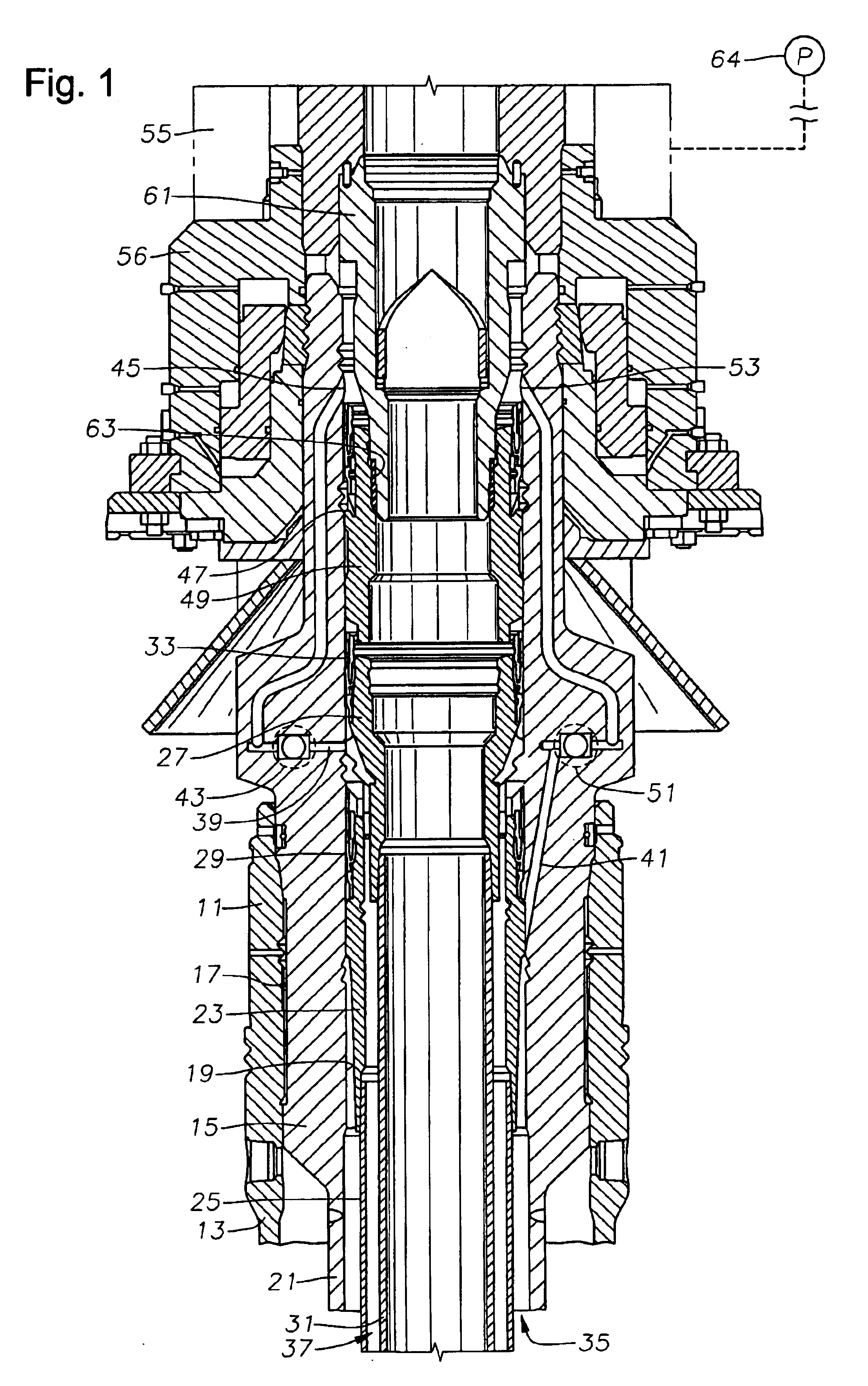
A susbsea well has communication passages to enable annulus pressure surrounding inner and intermediate strings of casings to be monitored at the surface. The passages both have outlets that allow communication to the tree assembly for monitoring. In one embodiment, the passage outlets are located in the bore of the high pressure well head housing and communicates to the tree assembly along an isolation sleeve. In another embodiment, the passage outlets are located on the exterior of the high pressure wellhead housing and communicate through a flying lead coming down from the tree. In another embodiment, the passage outlets are located on the exterior of the high pressure wellhead housing and communicate to an upward facing connection which is stabbed with a downward facing connection coming down from the tree.

Description

This invention relates in general to offshore drilling and production equipment, and in particular to a subsea well system for monitoring the pressure in a non-producing string of casing through the completion system.DESCRIPTION OF THE RELATED ARTA subsea well that is capable of producing oil or gas will have a conductor housing secured to a string of conductor pipe which extends a first depth into the well. A wellhead housing lands in the conductor housing. The wellhead housing is secured to an outer or first string of casing, which extends through the conductor to a deeper depth into the well. Depending on the particular conditions of the geological strata above the target zone (typically, either an oil or gas producing zone or a fluid injection zone), one or more additional casing strings will extend through the outer string of casing to increasing depths in the well until the well is cased to the final depth. Each string of casing is supported at the upper end by a casing hanger...

Claims


Application Information

Patent Timeline
Patent Type & Authority Patents(United States)
IPC IPC(8): E21B33/03E21B33/035E21B33/043
CPCE21B33/035E21B33/043E21B41/08E21B33/0353E21B33/14
Inventor BUCKLE, KEVIN G.OSBORNE, JOHN H.HUMPREY, BERNARDCLARK, ALAN M.MASSIE, ALFRED
Owner ABB VETCOGRAY
Learn More