Snowboard binding system

a technology of binding system and snowboard, which is applied in the direction of ski binding, snowboard binding, skiing, etc., can solve the problems of requiring a significant amount of effort, the knees not always straight when wearing inclined snowboard boots, and the inability of the snowboard to turn in the direction of the snowboard

Inactive Publication Date: 2004-05-11
SHIMANO INC
View PDF17 Cites 27 Cited by
  • Summary
  • Abstract
  • Description
  • Claims
  • Application Information

AI Technical Summary

Benefits of technology

Yet another object of the present invention is to provide a snowboard binding which eliminates the rear binding beneath the sole of the snowboard boot.
Still another object of the present invention is to provide a snowboard binding that is relatively simple and inexpensive to manufacture and assemble.
Still another object of the present invention is to provide a snowboard binding that is relatively lightweight.
Yet still another object of the present invention is to provide a snowboard binding, which reduces shock and improves power transfer between the sole of the snowboard boot and the snowboard binding.

Problems solved by technology

Similarly, leaning forward causes the board to tilt in a corresponding manner and thus causing the snowboard to turn in that direction.
Therefore, standing up straight with knees straight when wearing inclined snowboard boots is not always comfortable.
The lean forward requires a significant amount of effort due to the overall rigidity of the snowboard boots and therefore the bar configuration, especially in the snow and cold, can be difficult for some riders to release and / or engage.
Sometimes these bindings are difficult to engage due to buildup of snow and or cold.
Moreover, these bindings can be difficult to release the snowboarder's boots.
Furthermore, these bindings can be uncomfortable when riding the snowboard due to continued shock between the snowboard boots and the bindings.

Method used


Image

  • Snowboard binding system
  • Snowboard binding system
  • Snowboard binding system

Examples


third embodiment

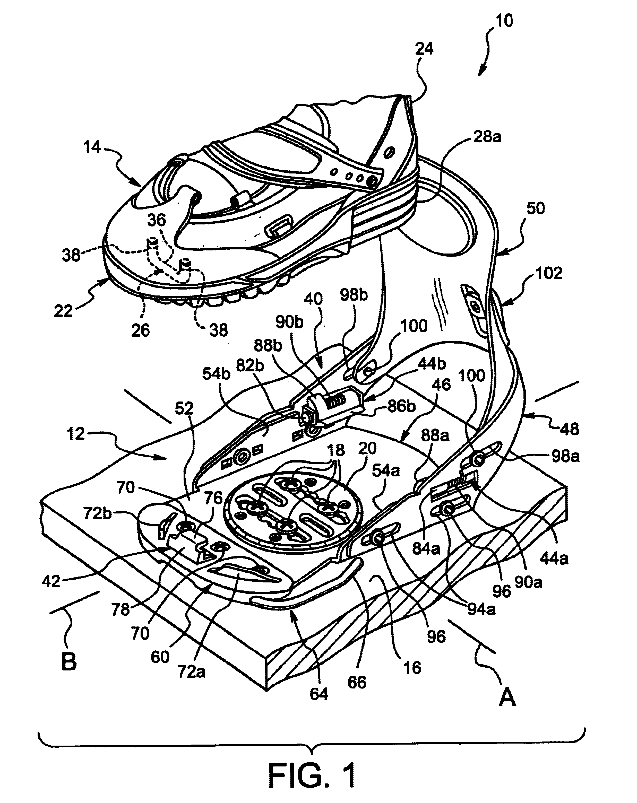
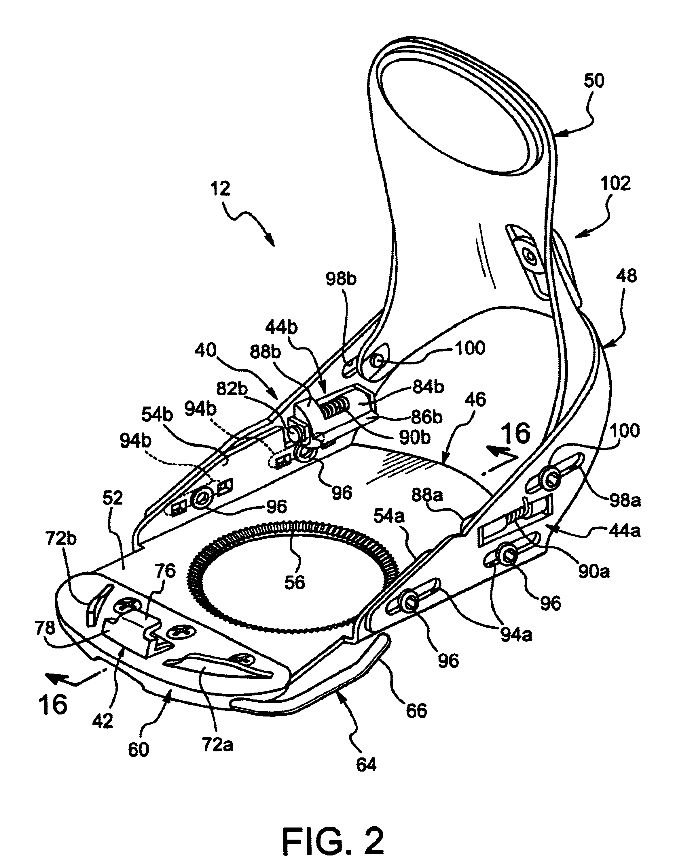
Referring now to FIG. 19, a snowboard binding 312 is illustrated in accordance with a third embodiment of the present invention. The snowboard binding 312 of this third embodiment is substantially identical to the snowboard binding 12 of the first embodiment except the snowboard binding 312 utilizes a base member 340 which is a modified version of the base member 40 of the first embodiment. The snowboard binding 312 is designed to be used with a snowboard boot identical or substantially identical to the snowboard boot 14 of the first embodiment. Since the snowboard binding 312 of this third embodiment is substantially identical to snowboard binding 12 of the first embodiment, the snowboard binding 312 will not be discussed or illustrated in detail herein. Rather, the following description will focus mainly on the differences. Moreover, it will be apparent to those skilled in the art that most of the descriptions of snowboard binding system 10, the snowboard binding 12 and the snowbo...

fourth embodiment

Referring now to FIG. 20, a portion of a snowboard binding system 410 is illustrated in accordance with a fourth embodiment of the present invention. The snowboard binding system 410 of this fourth embodiment is substantially identical to the snowboard binding system 10 of the first embodiment, except the snowboard binding system 410 includes a base member 440, which is a modified version of the base member 40 of the first embodiment. The snowboard binding system 410 has a snowboard binding 412, which is designed to be used with a snowboard boot identical or substantially identical to snowboard boot 14 of the first embodiment. Since the snowboard binding system 410 is substantially identical to snowboard binding system 10 of the first embodiment, the snowboard binding system 410 will not be discussed or illustrated in detail herein. Rather, the following description will focus mainly on the differences. Moreover, it will be apparent to those skilled in the art that most of the descr...

fifth embodiment

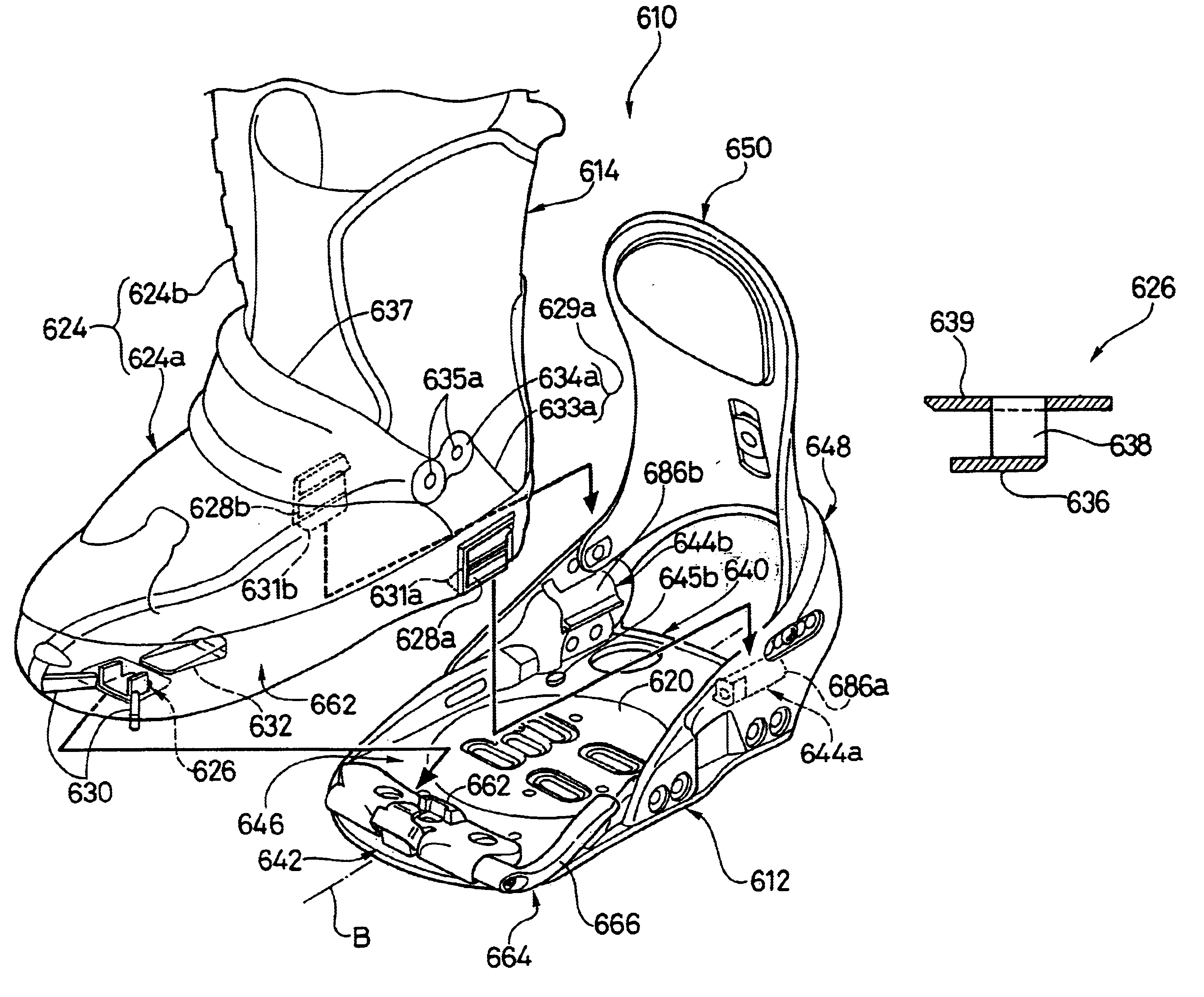
Referring now to FIGS. 21-45, a modified snowboard binding 512 and a modified snowboard boot 514 are illustrated in accordance with a fifth embodiment of the present invention. The snowboard binding 512 of this fifth embodiment is identical to the snowboard binding 12 of the first embodiment, except that the front binding arrangement of the snowboard binding 512 has been modified from the front binding arrangement of the snowboard binding 12 of the first embodiment as discussed below. Thus, the remaining parts of the snowboard binding 512 are identical to the snowboard binding 12 of the first embodiment. Since the snowboard binding 512 of the fifth embodiment is substantially identical to the snowboard binding 12 of the first embodiment, the snowboard binding 512 will not be discussed or illustrated in detail herein. Rather, the following description will focus mainly on the differences of the snowboard binding 512 from the snowboard binding 12. Moreover, it will be apparent to thos...


PUM


Abstract

A snowboard binding system includes a boot and a binding configured to be releasably coupled together. The snowboard binding includes a base member, a rear binding arrangement, and a front binding arrangement. The snowboard boot includes an upper portion, a sole portion, at least one rear catch and a front catch. The sole portion has a forward to rearward longitudinal axis extending between a toe section and a heel section. The rear catch is located at the heel section of the sole portion. The front catch is coupled to the toe section. The front catch has a pair of leg portions extending downwardly from the toe section and a tongue portion extending laterally between the leg portions. The tongue portion has a forward to rearward dimension that is larger than forward to rearward dimensions of the leg portions to longitudinally secure the boot relative to the binding.

Description

1. Field of the InventionThe present invention generally relates to a snowboard binding system for releasably coupling a snowboard boot to a snowboard. More specifically, the present invention relates to a snowboard binding system that has a boot with a relatively long front catch tongue to keep the boot in place relative to the binding.2. Background InformationIn recent years, snowboarding has become a very popular winter sport. In fact, snowboarding was also an Olympic event during the winter games at Nagano, Japan. Snowboarding is similar to skiing in that a rider rides down a snow covered hill. The snowboard is generally shaped as a small surfboard or a large skateboard without wheels. The snowboarder stands on the snowboard with his or her feet generally transverse to the longitudinal axis of the snowboard. Similar to skiing, the snowboarder wears special boots, which are fixedly secured to the snowboard by a binding mechanism. In other words, unlike skiing, the snowboarder has...

Claims


Application Information

Patent Timeline
Patent Type & Authority Patents(United States)
IPC IPC(8): A43B13/02A43B13/12A43B5/04A63C9/00A63C5/00A63C10/10A63C10/18A63C10/20A63C10/24
CPCA43B5/0401A43B5/0403A43B5/0423A43B5/049A43B13/12A63C10/10A63C10/103A63C10/106A63C10/20A63C10/24A63C10/18
Inventor OKAJIMA, SHINPEIMORITA, HIROSHITAKAHAMA, KIMITAKA
Owner SHIMANO INC
Why Eureka
Try Eureka