Glued screens for shale shakers

a technology of shale shaker and glued screen, which is applied in the direction of filtration separation, separation process, and wellbore/well accessories, etc., can solve the problems of increasing wear on mud pumps and other mechanical equipment used for drilling, weight, viscosity and gel problems in mud,

a technology of shale shaker and glued screen, which is applied in the direction of filtration separation, separation process, and wellbore/well accessories, etc., can solve the problems of increasing wear on mud pumps and other mechanical equipment used for drilling, weight, viscosity and gel problems in mud,

US6736270B2Inactive Publication Date: 2004-05-18VARCO I P INC

Image

  • Glued screens for shale shakers
  • Glued screens for shale shakers
  • Glued screens for shale shakers

Examples


Embodiment Construction

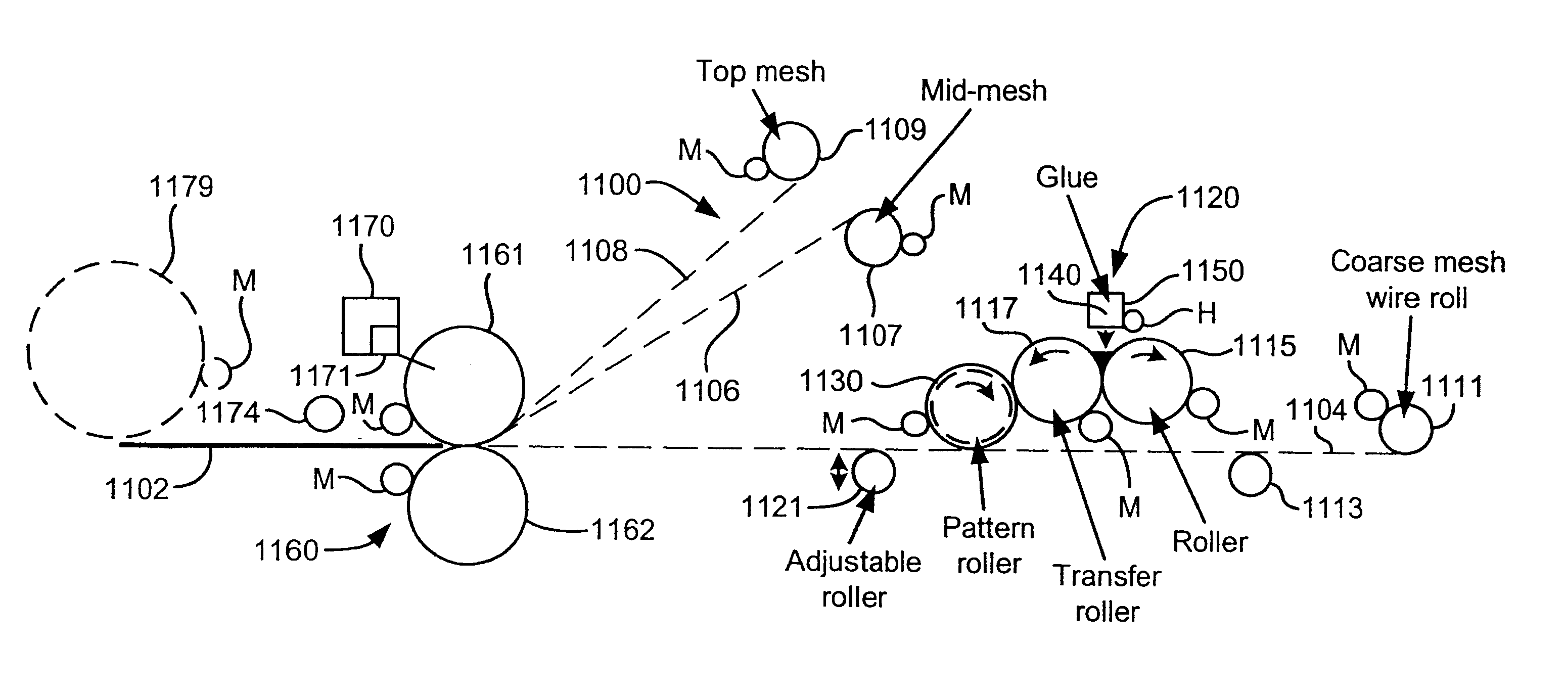
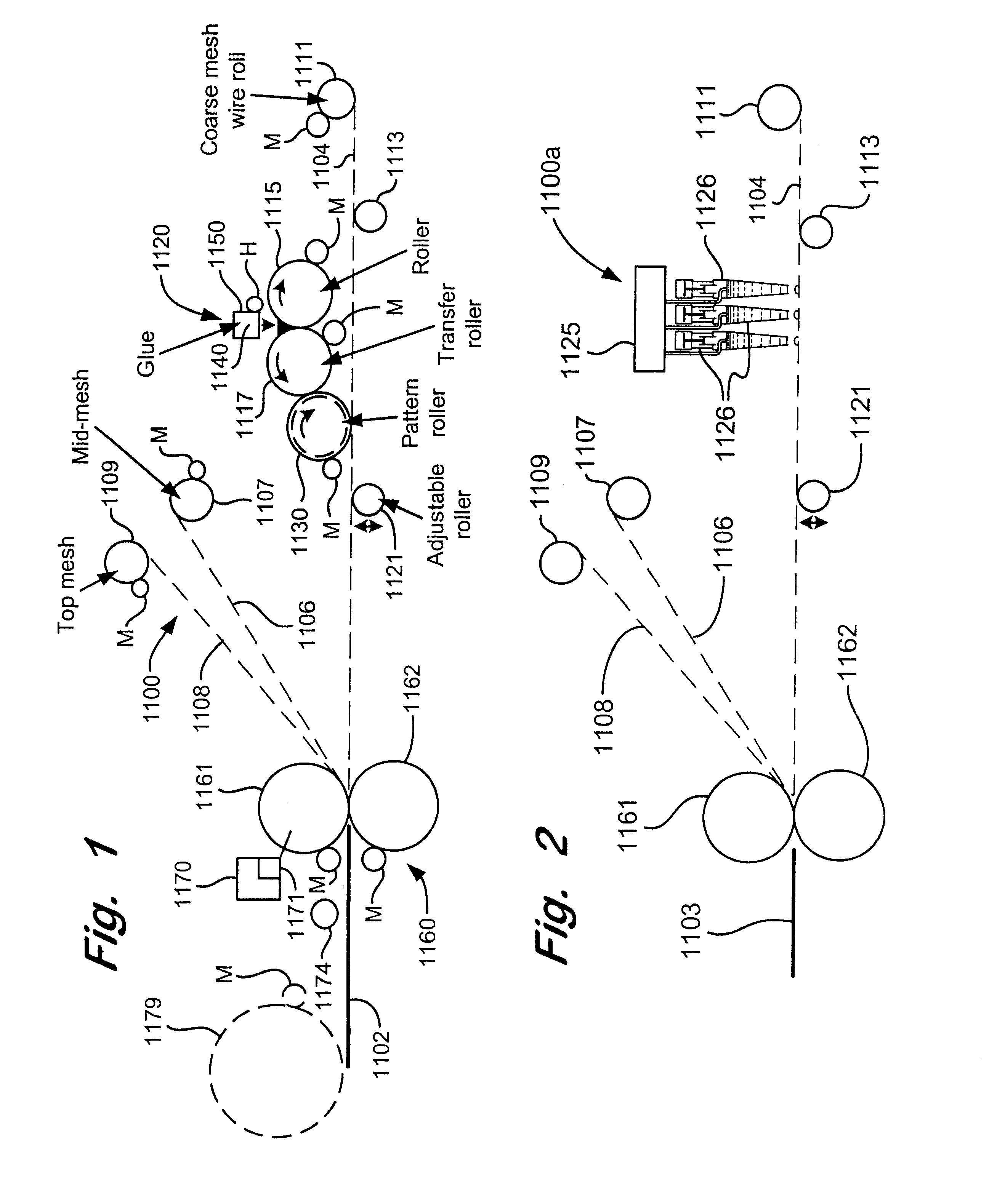
FIG. 1 shows a system 1100 according to the present invention for making a screen 1102 according to the present invention by a method according to the present invention. As shown the system 1100 produces a screen 1102 which includes a lower coarse mesh or screen 1004, an intermediate mesh or screen 1106, and a top mesh or screen 1108. Any one of these meshes (or screens) 1104, 1106, 1108 may be deleted. Alternatively one or more additional mesh layers may be added.

The coarse mesh 1104 is initially wound on a roller 1111 from which it is unwound and passes over a rotating roller 1113. From the roller 1113 the coarse mesh moves to a position beneath a gluing station 1120 where heated glue in a pattern is applied on the coarse mesh 1104. In one aspect the coarse mesh is 19 mesh made of wire with a diameter of about 0.126 inches. Of course any suitable mesh may be used. Sufficiently viscous hot melt glue is used which does not pass through and away from the mesh to which it is applied.

A...


PUM

PropertyMeasurementUnit
Lengthaaaaaaaaaa
Widthaaaaaaaaaa

Abstract

Screens and screen assemblies for a vibratory separator or shale shaker, such screens and screen assemblies made by a method including applying glue in a glue pattern to at least one layer of screening material, said applying done by powered moving mechanical glue application apparatus; in one aspect moving with powered mechanical screen movement apparatus the at least one layer of screening material beneath the powered moving mechanical glue application apparatus; in one aspect, using hot melt moisture-curing glue, and in one aspect facilitating the cure of moisture-curing glue by applying moisture to it.

Description

1. Field of the InventionThe present invention is directed to glued screens for vibratory separator apparatuses and shale shakers; to methods for making such screens; to automated methods for making such screens; to screens made by such methods; to machines for making such screens, and to vibratory separator apparatuses and shale shakers with such screens.2. Description of Related ArtThe need for solids control in drilling mud used in hydrocarbon well drilling is well known in the prior art. Drilling mud, typically a mixture of clay and water and various additives, is pumped down through a hollow drill string (pipe, drill collar, bit, etc.) into a well being drilled and exits through holes in a drillbit. The mud picks up cuttings (rock) and other solids from the well and carries them upwardly away from the bit and out of the well in a space between the well walls and the drill string. At the top of the well, the solids-laden mud is discharged over a shale shaker, a device which typi...

Claims


Application Information

Patent Timeline
18 May 2004
Publication
US6736270B2
IPC
B01D29/01; B01D33/03; B01D33/00; B07B1/48; B07B1/49; B07B1/00; B07B1/46; B21F27/00
CPC
B01D29/012; B01D33/0093; B01D33/0384; B07B1/00; B07B1/4618; B07B1/4645; B07B1/4654; B07B1/4663
Inventors
ADAMS, THOMAS C.; WARD, KERRY