Waterstop for foundation elements and method of installation

a foundation element and water stop technology, applied in the direction of soil conditioning compositions, applications, roads, etc., can solve the problems of water leakage through the joint, loss of intimate contact between, and concrete not bonding well to rubber or pvc, etc., to achieve convenient installation

Inactive Publication Date: 2004-05-25
KVAERNER CEMENTATION FOUND LTD
View PDF20 Cites 19 Cited by
  • Summary
  • Abstract
  • Description
  • Claims
  • Application Information

AI Technical Summary

Benefits of technology

According to a third aspect of the present invention, there is provided a foundation element having a waterstop formed therein, wherein the waterstop comprises one or more longitudinal strips of hydrophilic material, wherein the hydrophilic strips extend vertically from a position at or near the top of the foundation element to a position at or near the base of the element.
The waterstop of the present invention is conveniently installed in the secondary elements after the formation of the primary elements. For example, in the case of a diaphragm wall, a series of alternate "primary" panels are constructed, and the region between each pair of primary elements is e

Problems solved by technology

As is well-known, concrete does not bond well to rubber or PVC; therefore, loss of intimate contact can occur between the concrete foundation element and the waterbar.
There is therefore a risk that water will leak through the joint.
There are a number of limitations/problems associated with known waterbar systems.
However, in some underground structures it may not always be possible or desirable to use stop-ends between adjacent elements.
In these cases a waterbar can not be installed and so if the installation of a waterbar is required, the choice of construction of the diaphragm wall panels is restricted.
Stop-ends are not normally used, in which case it is not possible to install a waterb

Method used


Image

  • Waterstop for foundation elements and method of installation
  • Waterstop for foundation elements and method of installation
  • Waterstop for foundation elements and method of installation

Examples


Embodiment Construction

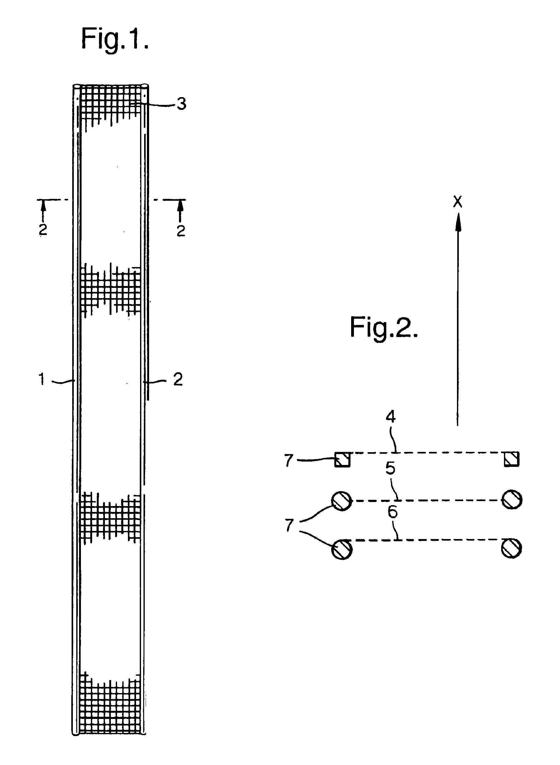
FIG. 1 shows a waterstop of the present invention comprising two longitudinal hydrophilic cords 1 and 2, which are separated and supported by a support element 3 which is made of geotextile or any other suitable material. A section 2--2 through FIG. 1 is shown in FIG. 2 and comprises a series of waterstop members 4, 5 and 6 which are substantially parallel to each other. By way of illustration, the cross-sectional shape of the hydrophilic cords 7 are shown to be either square or circular. It should be appreciated that the cross section of the hydrophilic cords is not critical and that many alternative shapes are envisaged. Furthermore, the point of attachment of the support to the cords is not critical.

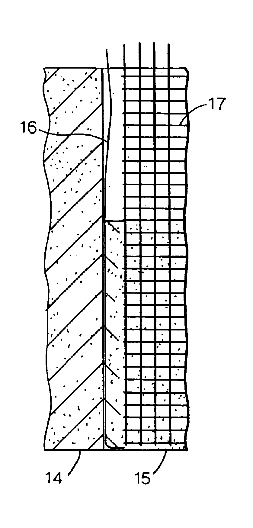
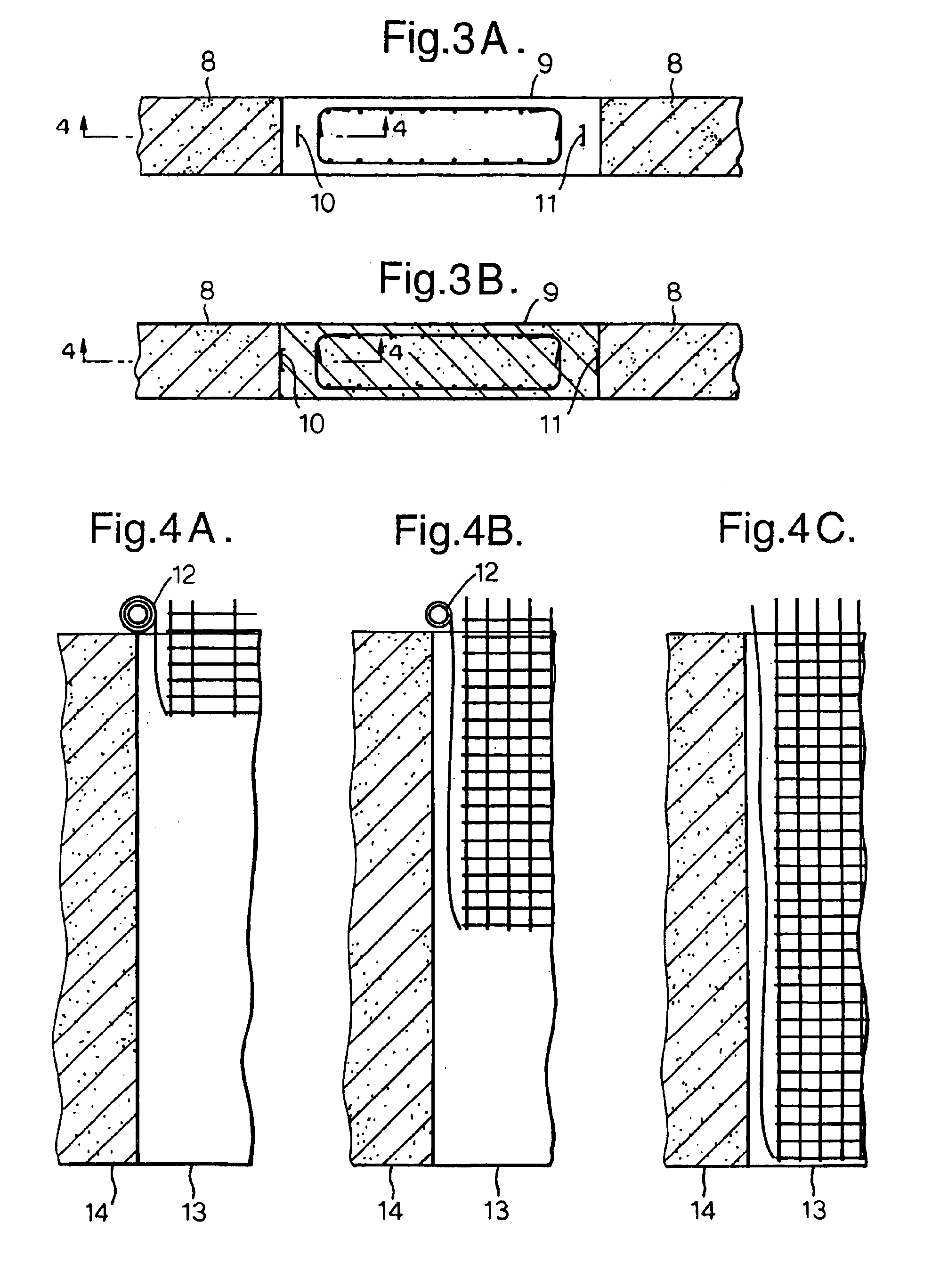
FIG. 3 shows a plan view of a series of diaphragm wall panels comprising alternate "primary" panels 8, and an excavated bore 9, for a secondary panel. FIG. 3A illustrates the position of two waterstops 10 and 11 in the excavated bore. Each waterstop is lowered into the bore at a posit...


PUM

PropertyMeasurementUnit
Flow rateaaaaaaaaaa
Lengthaaaaaaaaaa
Hydrophilicityaaaaaaaaaa

Abstract

A waterstop, 10 or 11, for restricting or preventing the flow of water across the joints of foundation elements 8, such as between or along individual diaphragm wall panels or between or along individual secant wall piles. The present invention also relates to a method of installing a waterstop at or near the joints between adjacent foundation elements. The waterstop consists of one or more longitudinal strips, 1 or 2, of hydrophilic material, wherein the or each hydrophilic strip extends vertically along the interface between adjacent foundation elements, from a position at or near the top of the foundation elements, to a position at or near the base of the elements.

Description

1. Technical Field of the InventionThe present invention relates to an apparatus for restricting or preventing the flow of water across the joints of foundation elements, such as between or along individual diaphragm wall panels or between or along individual secant wall piles. The present invention also relates to a method of installing a waterstop at or near the joints between adjacent foundation elements.2. Prior ArtA diaphragm wall is made by casting a series of concrete panels, which may be reinforced, in excavated trenches as described, for example, in EP 0 101 350 and EP 0 402 247. In some cases, alternate `primary` panels are constructed first, followed by infill (i.e. closing) `secondary` panels. The installation sequence would be, for example, panels 1, 3, 5, 7, 9, 11 etc. followed by panels 2, 4, 6, 8, 10 etc. In other cases, only a few `primary` panels are first constructed, for example panels 1, 10 and 20. Following this, a series of `continuity` panels 2, 11, 3, 12 etc...

Claims


Application Information

Patent Timeline
IPC IPC(8): E04B1/68E02D5/18E04B1/686
CPCE02D5/185E04B1/6806
Inventor SHOTTON, PETER GILBERT
Owner KVAERNER CEMENTATION FOUND LTD
Why Eureka
Try Eureka