Projector

a projector and projector technology, applied in the field of projectors, can solve the problems of increased noise likely to be generated in using the projector, increased sound of the exhaust fan itself and the jet noise, and naturally increased flow rate and speed of the cooling air

Inactive Publication Date: 2004-06-08
SEIKO EPSON CORP
View PDF10 Cites 15 Cited by
  • Summary
  • Abstract
  • Description
  • Claims
  • Application Information

AI Technical Summary

Benefits of technology

As the centrifugal fan, a fan for inhaling air from a rotary surface of a fan and discharging in tangential direction of the rotation of the vane, which may be a sirocco fan etc. The centrifugal fan inhales air with a large opening area and discharges the air with a small opening area, so that the discharge pressure of the discharged air can be magnified.
According to the above arrangement, the lid member and the partition members do not have to be manufactured as separate components, thereby omitting work and components required therefor.

Problems solved by technology

However, following problems accompanies in the above arrangement where the fan is enlarged in accordance with increasing the luminance of the light source for enhancing the cooling efficiency.
When the size of the fan is increased to promote circulation of the cooling air inside the device, flow rate and speed of the cooling air are naturally increased, which causes jet noise in colliding with the components constituting the projector, so that noise is likely to be generated in using the projector.
Especially, when the exhaust fan is provided along the exterior case of the projector, size increase of the fan results in increase in the sound of the exhaust fan itself as well as the jet noise, thus further increasing the noise.
Further, in the conventional projector, since the cooling air is exhausted from a backside of the device opposite to the portion provided with the projecting optical system, hot wind is blown to the audience observing the projected image, which is annoying to the audience.

Method used


Image

  • Projector
  • Projector
  • Projector

Examples


Embodiment Construction

)

An embodiment of the present invention will be described below with reference to attached drawings.

[1. Primary Arrangement of Projector]

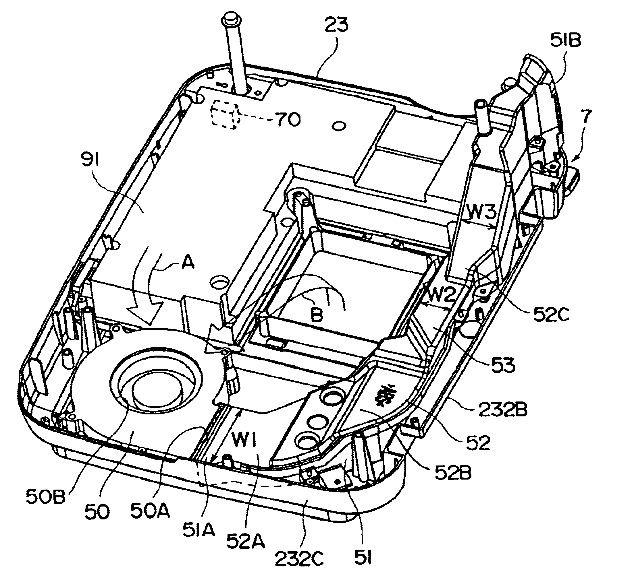
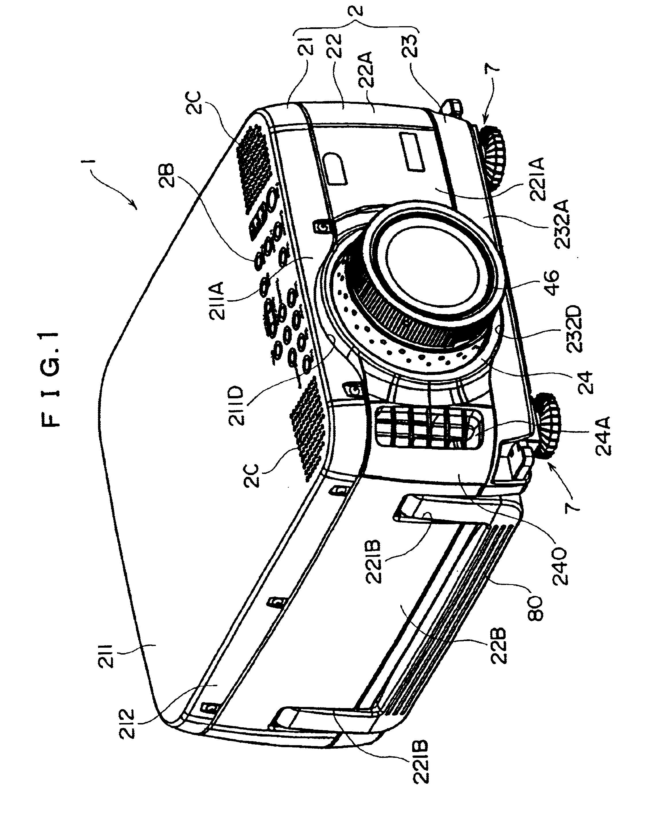
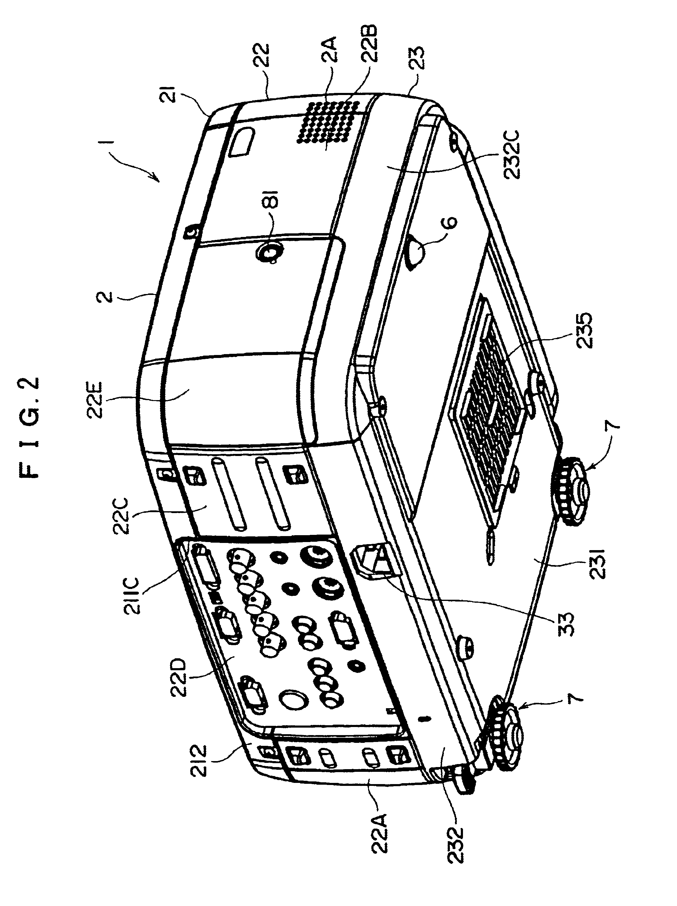
In FIGS. 1 to 3, a projector 1 has an exterior case 2, a power supply unit 3 accommodated in the exterior case 2, and an optical unit 4 of planarly L-shape disposed in the exterior case 2, the entirety of the projector 1 being approximate rectangular solid.

The exterior case 2 includes a sheet-metal upper case 21, a middle case 22 made of bent aluminum or steel plate, and a lower case 23 made of die casting such as magnesium. The cases 21, 22 and 23 are mutually fixed by a screw.

The upper case 21 is formed of an upper portion 211 and a side portion 212 disposed around the upper portion 211, which is, for instance, shaped by a press using a die. A circular hole 211D corresponding to a lens attachment frame 24 for attaching a projector lens 46 is provided to a front portion 211A side of the side portion 212, the neighborhood of the circular hole 211D ...


PUM

PropertyMeasurementUnit
bending angleaaaaaaaaaa
aspect ratioaaaaaaaaaa
cross-sectional areaaaaaaaaaaa

Abstract

A centrifugal fan (50) is provided around the light source of the projector and an exhaust duct (51) is connected to the centrifugal fan with at least one of bent portion (52) for bending exhaust stream from the centrifugal fan being formed on the exhaust duct. Since the centrifugal fan for exhausting air can be disposed at a position remote from the exhaust hole, the noise generated from the projector can be reduced even when the size of the cooling fan is increased.

Description

1. Field of the InventionThe present invention relates to a projector having a light source, an electric optical device for modulating a light beam irradiated from the light source in accordance with image information to form an optical image, a projecting optical system for enlarging and projecting the optical image formed by the electric optical device, and a casing for accommodating these components.2. Description of Related ArtConventionally, a projector having a light source, an electric optical device for modulating a light beam irradiated from the light source in accordance with image information to form an optical image, a projecting optical system for enlarging and projecting the optical image formed by the electric optical device, and a casing for accommodating these components has been used.Such projectors have been widely used for multimedia presentation in a meeting, scientific society, exhibition etc. Accordingly, in order to obtain vivid projected image by the project...

Claims


Application Information

Patent Timeline
Patent Type & Authority Patents(United States)
IPC IPC(8): H04N5/74G03B21/16G09F9/00G02F1/13
CPCH04N9/3141
Inventor NAKANO, HIROHISAWATANABE, NOBUOYAMADA, HARUYOSHI
Owner SEIKO EPSON CORP
Why Eureka
Try Eureka