Flaw detection in tubular members

a technology of flaw detection and ultrasound, applied in the field of ultrasound systems and methods for detecting flaws in tubular members, can solve the problems of inability to accurately examine a defect, time-consuming and expensive replacement or repair of a defective tubular, and inability to detect the d

Inactive Publication Date: 2004-06-15
VARCO I P INC
View PDF66 Cites 65 Cited by
  • Summary
  • Abstract
  • Description
  • Claims
  • Application Information

AI Technical Summary

Benefits of technology

Such systems and methods which can effectively and efficiently inspect nearly all of the length of tubular members, etc. relatively near (e.g. within a few millimeters or within an eighth of an inch) the ends thereof for both outer and inner surface defects;

Problems solved by technology

Flaws and defects in tubular members can result in the failure of the tubulars.
Replacement or repair of a defective tubular can be time-consuming and expensive.
In some cases, defects located on a surface (interior or exterior) of a tubular can be visually characterized and examined to determine whether removal of the defect is necessary and possible--and whether removal is feasible by grinding or other means; but often such visual examination of a defect is not accurate or is not possible.
Known automated ultrasonic systems for detecting flaws and defects in tubulars have been unable to adequately, accurately, and correctly detect inner surface defects relatively near the ends of the tubular member, e.g., within two feet or within eighteen inches of the ends up to the end boundary surface.
The ends of such tubulars are often examined manually with portable electromagnetic or ultrasonic testing equipment in a time-consuming process.
This inability to distinguish and differentiate these signals renders these systems and methods inadequate for inner surface defect detection near the tubulars' ends.
In many instances a signal reflected from a tubular end is misinterpreted as, is not easily distinguishable from or is indistinguishable from a signal reflected from an inner surface defect near a tubular end and such a signal often cannot be accurately analyzed to determine whether there is a defect near the tubular end.
A misinterpretation of such a signal can also result in a false indication of an inner surface defect.

Method used


Image

  • Flaw detection in tubular members
  • Flaw detection in tubular members
  • Flaw detection in tubular members

Examples


Embodiment Construction

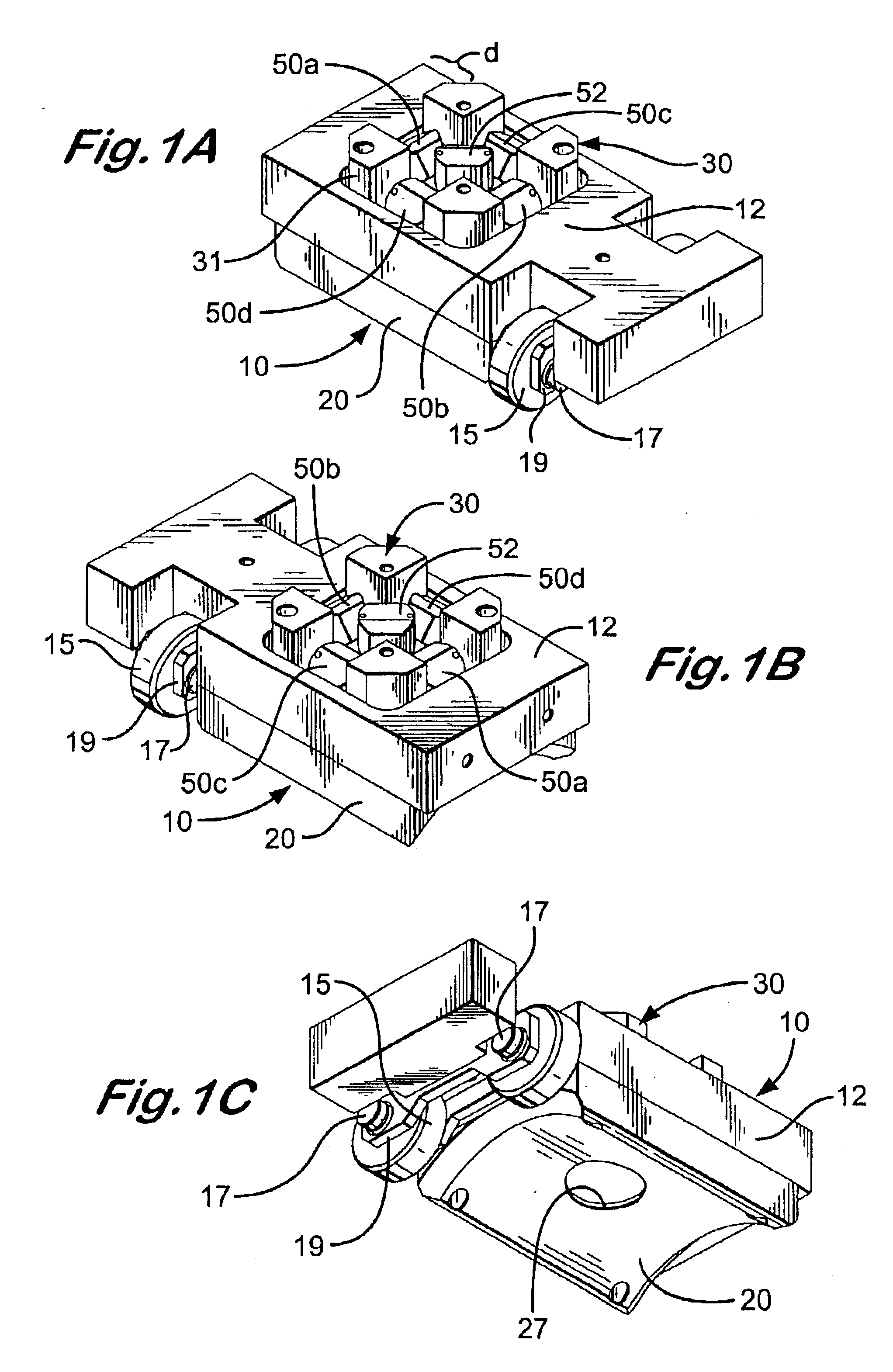
FIGS. 1A-1C show a transducer device 10 according to the present invention for use with tubular inspection systems. The device 10 has a base 12; a waveguide support 30; ultrasonic transducers 50a-50d and 52 on the waveguide support 30; and a wearplate 20 secured over one surface of the waveguide member 30.

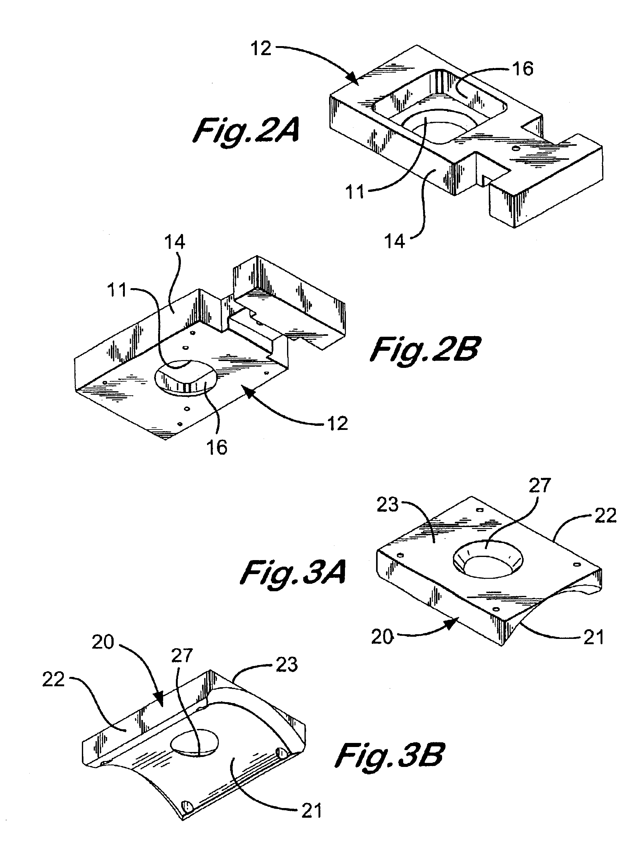
FIGS. 2A-2E show details of the base 12 of the device 10 of FIG. 1. The base 12 has a body 14 with a recess 16 in which is positioned the waveguide support 30. A bevelled opening 11 receives a correspondingly shaped part of the waveguide support 30 as described below. A roller assembly is secured to the base 12 and has rollers 15 secured to a spacer 19 by bolts 17. These rollers 15 contact the outer surface of a tubular along which the device 10 is moved.

FIGS. 3A and 3B show the wearplate 20 which has a body 22; front face 21; a beveled opening 27 corresponding in size and location to the opening 11 of the base 12 and through which projects part of the waveguide support 30 as discu...


PUM

PropertyMeasurementUnit
anglesaaaaaaaaaa
anglesaaaaaaaaaa
anglesaaaaaaaaaa

Abstract

A method, in at least certain aspects, for ultrasonically inspecting a tubular member, the tubular member having an inner surface, an outer surface, and two spaced-apart ends including a first end of the tubular member, the method including transmitting sonic beams to the tubular member with transducers such that sonic beams are reflected from the inner surface of the tubular member, the outer surface of the tubular member, and from the first end of the tubular member, sensing the first end of the tubular member, completing inspection of all or of substantially all of the outer surface of the tubular member for outer surface defects while continuing to inspect the inner surface of the tubular member for inner surface defects, continuing to inspect the inner surface of the tubular member for inner surface defects, the transducers continuing to transmit sonic beams for the inspection of the inner surface of the tubular member until the transducers are near the first end of the tubular member; and apparatus for such methods.

Description

1. Field of the InventionThe invention is directed to: ultrasonic systems and methods for detecting flaws in tubular members; in certain particular aspects, to such systems and methods that are automatic and which accurately detect flaws near or at the ends of a tubular member such as pipe, tubing, casing, or other oil field tubulars; and, in certain aspects, to systems and methods for detecting defects in welds in, on, or between tubular members.2. Description of Related ArtFlaws and defects in tubular members can result in the failure of the tubulars. Replacement or repair of a defective tubular can be time-consuming and expensive. In the oil and gas industries, tubular members used in drilling and other oil field operations are examined before use to detect and locate defects. Often a defect can be removed and the tubular used for its intended purpose. In other cases, the defect cannot be fixed and the tubular is rejected. Whether the tubular member can be used is based on charac...

Claims


Application Information

Patent Timeline
Patent Type & Authority Patents(United States)
IPC IPC(8): G01N29/26G01N29/11G01N29/38G01N29/22G01N29/265G01N29/36G01N29/04G01N29/06G01N29/07G01N29/24G01N29/44
CPCG01N29/0609G01N29/07G01N29/11G01N29/225G01N29/265G01N29/38G01N29/4445G01N2291/011G01N2291/015G01N2291/02854G01N2291/0421G01N2291/0422G01N2291/0427G01N2291/044G01N2291/051G01N2291/101G01N2291/105G01N2291/2634G01N2291/2636
Inventor LAM, CLIVE CHEMOKEMPER, JOSEPH GREGORYMANOCCHIO, ANTONIO
Owner VARCO I P INC
Why Eureka
Try Eureka