Control system for controlling the feeding and burning of a pulverized fuel in a glass melting furnace

a control system and glass melting furnace technology, applied in glass furnace equipment, lighting and heating equipment, combustion process, etc., can solve the problems of inconvenient unit melter technology, inconvenient oxy-fuel process, and inconvenient oxygen itself cost,

Inactive Publication Date: 2004-06-15
VITRO GLOBAL
View PDF21 Cites 20 Cited by
  • Summary
  • Abstract
  • Description
  • Claims
  • Application Information

AI Technical Summary

Benefits of technology

Another objective of the present invention is to provide a control system for feeding pulverized fuel in a glass melting furnace, which allows a coordinated operation sequence among all different systems that interact along the whole process of storing, handling, transporting, feeding, burning and disposing of the pulverized fuel in the glass melting process. The interaction of control system takes place between the combustion control system with a feeding control system, a melter control system, an environmental control system, a waste handling control system, and a storage and transportation control system, in order to carry out the data interchange of all the variables manipulated and detected in the different stages of the process and equipments and for feeding the pulverized fuel to a plurality of burners that are associated with a pair of sealed regenerators of a regenerative glass melting furnace.

Problems solved by technology

However there is an enormous heat loss in the glass leaving high-temperature operating furnaces.
This technology has the inconvenient of requiring a unit melter furnace with a special preparation of the refractories since air infiltration need to be prevented.
Another inconvenient for the oxy-fuel process is the cost of the oxygen itself.
However, the continuing upward spiral of energy costs (primarily natural gas) have forced the major float glass manufacturers to add "surcharges" to truckloads of flat glass.
However, due to the high sulfur content and vanadium the use of petroleum coke as fuel is not common in the glass industry, due to the negative effect on the structure of the refractories and in addition the environmental problems.
Vanadium oxide is one of metals that represents a source of damage to basic refractories, because the acid behavior of this oxide in gaseous state.
On the other hand, the main problem with the use of the petroleum coke is related with the high sulfur and vanadium content, which have a negative effect on the structure of the refractories in the furnaces.
However, as was described of the above, the effect of the vanadium on the refractories produce a great amount of problems in the glass furnaces, which has not solved in its totallity
Another problem of the use of the petroleum coke is related with the environment.
The high content of sulphur and metals as nickel and vanadium produced by the combustion of the petroleum coke have provoked environmental problems.
Processing techniques for the reduction of gaseous emissions are essentially restricted to the proper selection of firing fuels and raw materials, as well as to furnace design and operation.
Where large volumes of flue gas from industrial furnaces must be purified, purification is adversely affected by the formation of gas streaks with widely varying sulphur dioxide concentrations.

Method used


Image

  • Control system for controlling the feeding and burning of a pulverized fuel in a glass melting furnace
  • Control system for controlling the feeding and burning of a pulverized fuel in a glass melting furnace
  • Control system for controlling the feeding and burning of a pulverized fuel in a glass melting furnace

Examples


first embodiment

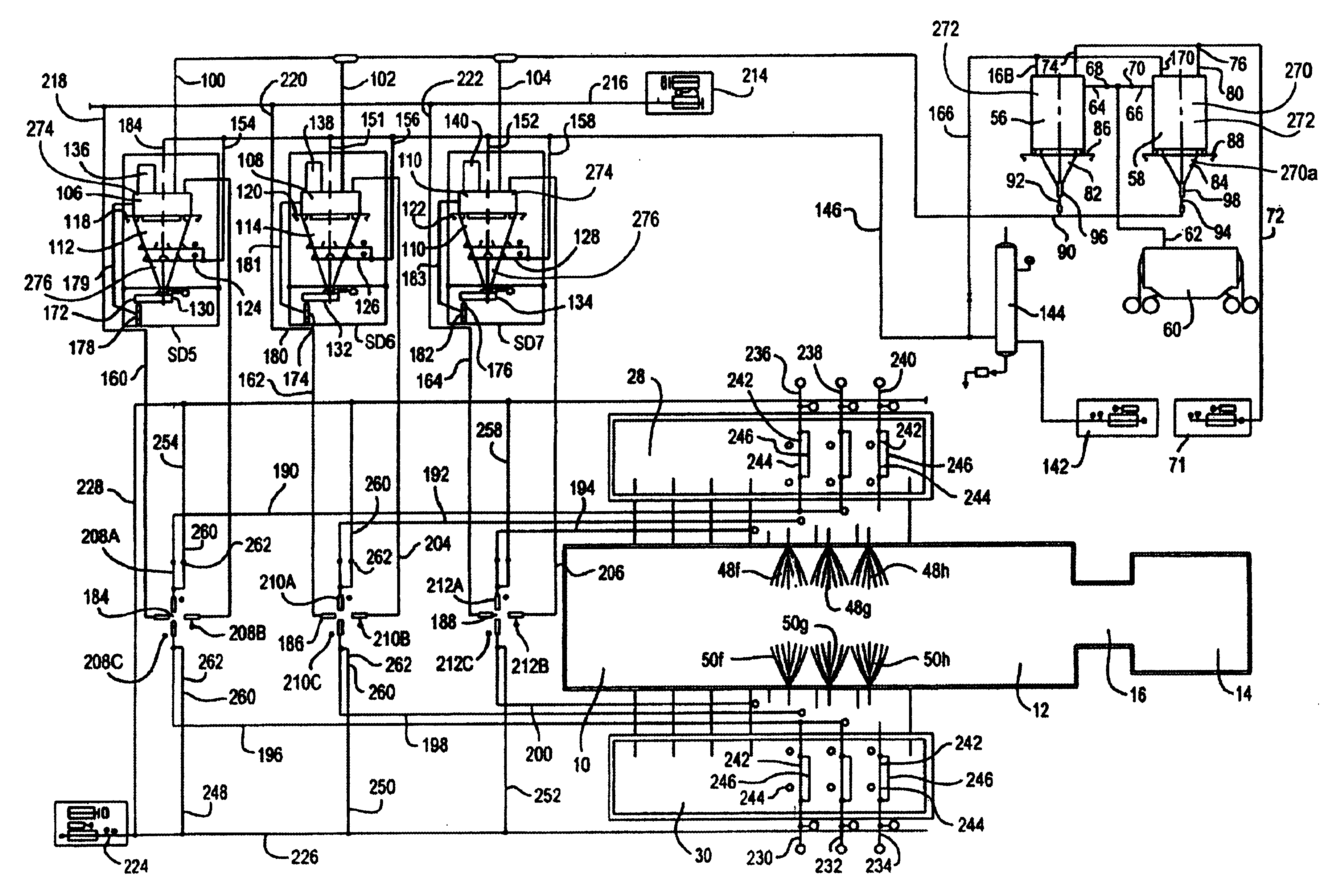
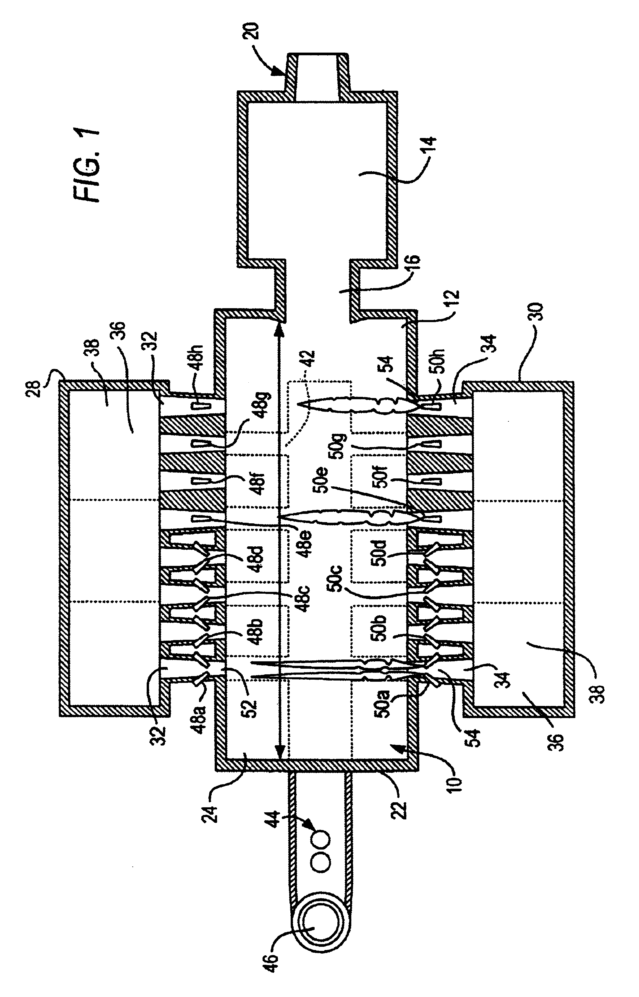
In a first embodiment, the pulverized fuel can be fed to the furnace in an intermittent sequence. In this case, in a first step, once that the combustion cycle has finished in one side of the furnace, the feeding of pulverized fuel to each of the burners,--for example burners 48f, 48g, 48h, by means of the pulverized fuel feeding systems SD-5, SD-6 and SD-7--are stopped. However, a continuous flow of the conveying air is maintained during a short period of time "as a purge" for cleaning purposes for that said pipes 192, 194 and 196. In this embodiment, the flow of the pulverized fuel is totally stopped in the pulverized fuel feeding systems SD-5, SD-6 and SD-7, meanwhile the combustion cycle is being changed from the burners 48f, 48g, 48h to the burners 50f, 50g and 50h to carry out a second combustion cycle. In this step, the furnace gates FG are open to initiate the feeding of pulverized fuel, for example toward burners 50f, 50g, 50h. In this second step, once the opposite side of...

second embodiment

In a second embodiment, the operation of the pulverized fuel feeding systems SD-5, SD-6 and SD-7, is maintained in a continuous form, in order to maintain a major and better stability in the feeding of the pulverized fuel to each of the burners. The arrangement is similar to previous example, but here is used the four-way valve 184, 186, 188 above described or a three way diverter valve that perform the same operation (not shown). Through this embodiment, the feeding of the pulverized fuel can be previously tested, calibrated and set up before said fuel be fed to each the burners 48a-to-h or 50a-to-h.

In this way, the air-fuel mixture that arrives through the third outlet pipes 160, 162, 164, is regulated by the four-way set of valves 184, 186 and 188 and ball valves 208A-to-C, 210A-to-C, 212A-to-C, for alternating the injection of the air-fuel mixture between the burners 48a-to-h and 50a-to-h. So, during the cycle change, meanwhile the furnace gates FG are being opened to initiate t...


PUM

PropertyMeasurementUnit
temperaturesaaaaaaaaaa
residence timeaaaaaaaaaa
temperatureaaaaaaaaaa

Abstract

A control system for controlling the storing, feeding and burning of a pulverized fuel in a glass melting furnace, wherein a series of burners are arranged one in front of the other to carry out combustion and non-combustion cycles during a glass melting process. Pulverized fuel feeding systems are provided, which are filled up and emptied out with the pulverized material for providing a constant flow of the pulverized fuel to each of the burners dunng the glass melting process. The control system including control means for monitoring and controlling the filled up and discharge out of said pulverized fuel feeding system based on the measurement and monitoring of the amount of pulverized fuel that is being storaged and feeded by the pulverized fuel feeding system. Control means are provided for monitoring at least one operating variable involved on the glass melting furnace, the control means detecting a series of different variable during the glass melting process. And means for controlling the alternation of the combustion and non-combustion cycles to each burner, based on the monitoring and feeding of the pulverized fuel to burner and in base to the operating variables of the glass melting process.

Description

1. Field of the InventionThe present invention is related to a control system for controlling the feeding and burning of a pulverized fuel in a glass melting furnace and, more specifically to a control system that feeds pulverized fuel in a glass melting furnace.2. Related Prior ArtMelting glass has been done for different kinds of furnaces as well as types of fuels, depending on the final characteristics of the product and also regarding the thermal efficiency of the melting and refining processes. Unit melter furnaces have been used to melt glass (by means of gas fuel), these furnaces have several burners along the sides of the furnace, the whole unit looks like a close box where there is a chimney that can be placed either in the beginning of the feeder or at the very end of the furnace, it means, going downstream. However there is an enormous heat loss in the glass leaving high-temperature operating furnaces. At 2500.degree. F., for example, the heat in the flue gases is 62 perc...

Claims


Application Information

Patent Timeline
Patent Type & Authority Patents(United States)
IPC IPC(8): C03B5/00C03B5/24C03B5/235F23N1/02F23K3/00F23K3/02F23N5/00
CPCC03B5/235C03B5/24F23N5/00F23N1/02F23K3/02
Inventor SOLIS-MARTINEZ, IVAN JORGE
Owner VITRO GLOBAL
Why Eureka
Try Eureka