
Method and apparatus for detecting processor congestion during audio and video decode

a technology processing methods, applied in the field of audio and video decoding, can solve problems such as unnatural gaps, jerkiness or slowness, and inability to keep up with real time, and achieve the effects of chaotic video images, unnatural gaps, and unnatural gaps

Inactive Publication Date: 2004-06-15
CISCO TECH INC
View PDF2 Cites 20 Cited by
  • Summary
  • Abstract
  • Description
  • Claims
  • Application Information

AI Technical Summary

Problems solved by technology

Failure to keep up with real time results in unnatural gaps, jerkiness, or slowness, in the motion video or audio presentation.
Prolonged failure to keep up with the incoming compressed data will eventually result in the overflow of some buffer and the loss of a valid video frame reference which, in turn, results in chaotic video images due to the differential nature of the compressive coding.
The processing power requirements of the operating system, digital video transmission independent software applications and the decompression algorithms described above, may cause the processor to become congested.
In addition, some portions of the coded video require more processing than others.
When an extended epoch of video of high computational complexity is received, the decoder may become congested.
When congested, processors may not have enough processing power to execute the decompression algorithms at a rate sufficient to keep up with the source of the encoded data.
Processor congestion is a state which is often incompatible with the real time requirements of digital video transmission.
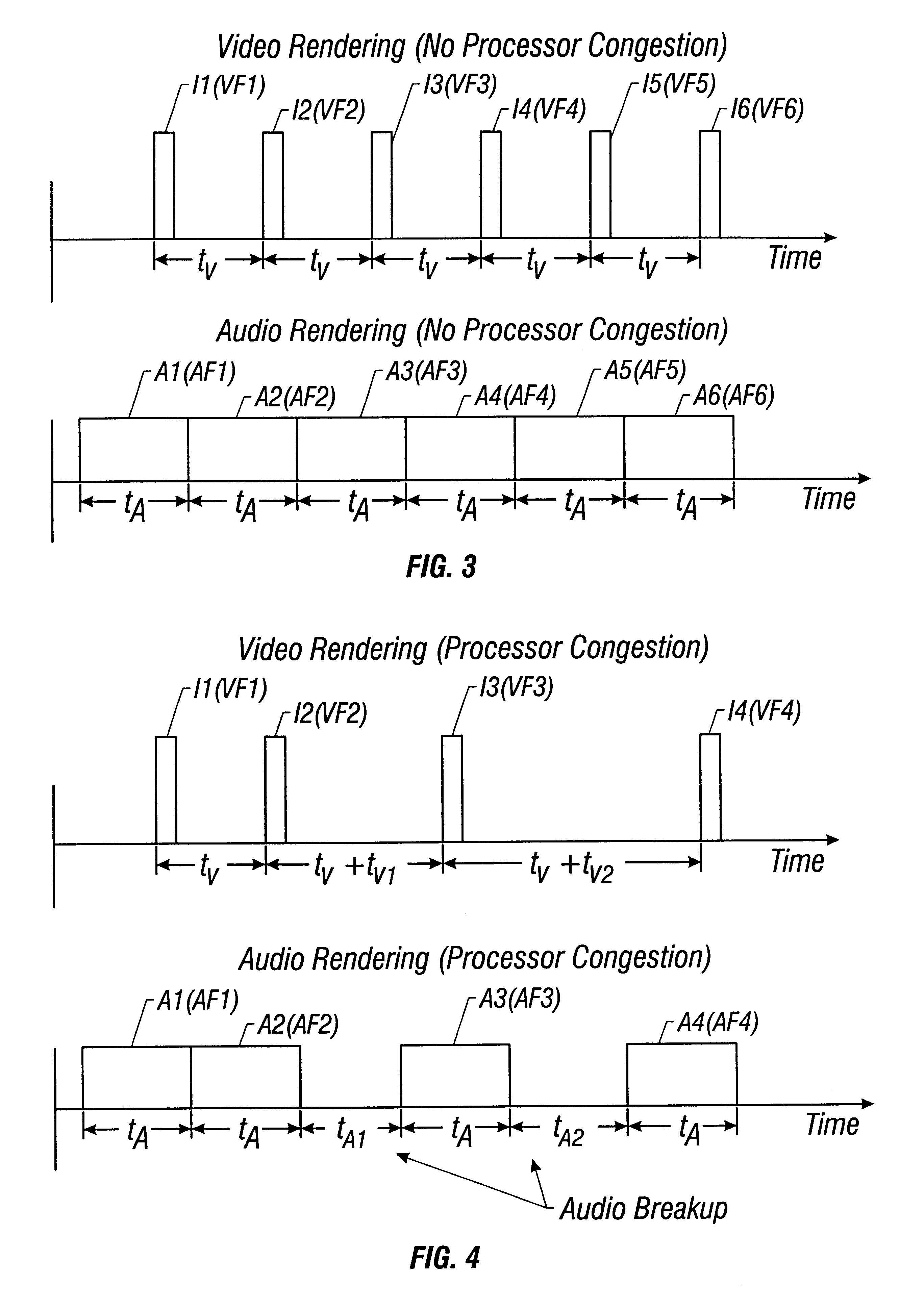
Audio artifacts occur when a noticeable time gap occurs between the generation of audio corresponding to any two consecutive frames of audio data.
The delay in audio generation manifests itself in the form of audio breakup.

Method used


Image

  • Method and apparatus for detecting processor congestion during audio and video decode
  • Method and apparatus for detecting processor congestion during audio and video decode
  • Method and apparatus for detecting processor congestion during audio and video decode

Examples


Embodiment Construction

The term system as used herein generally describes the hardware components that in combination allow the execution of software programs or algorithms. Hardware generally includes a processor, memory media, and input / output (I / O) devices. As used herein the term processor generally describes the logic circuitry that responds to and processes basic instructions. The term "memory medium" includes an installation medium, eg, a CD ROM, or floppy disks; a volatile computer system memory such as DRAM, SRAM, rambus RAM, etc.; or a non volatile memory such as optical storage or magnetic medium, eg, a hard drive. Rambus is a registered trademark of Rambus Inc. The term "memory" is used interchangeably with "memory medium" herein. The memory medium may comprise other types of memory or combinations thereof. In addition, the memory medium may be located in a system in which the programs are executed, or may be located in a second system that connects to the first system over a network. In this ...


PUM


Abstract

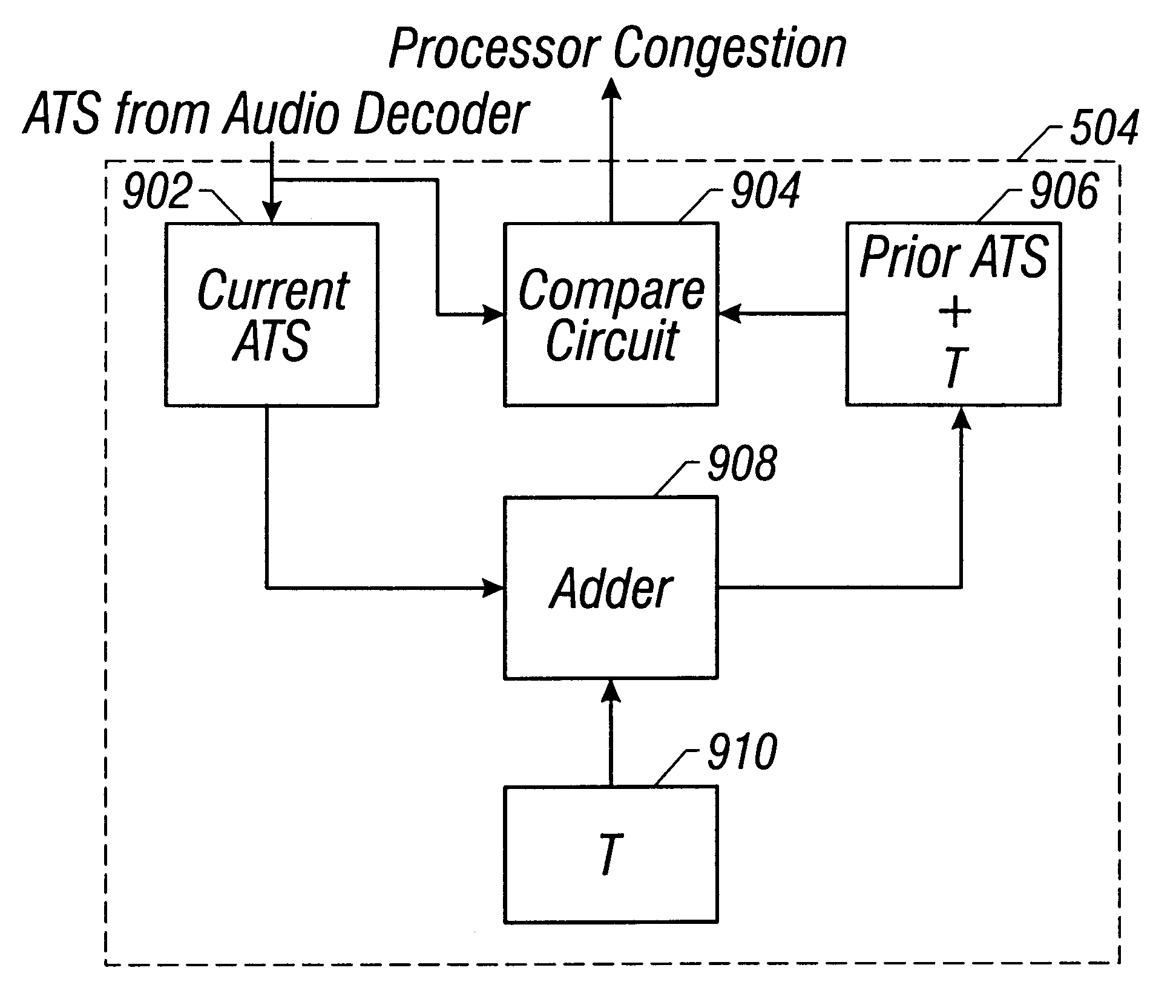
Disclosed is a method and system for detecting processor congestion during decompression of a stream of video and audio data. The system and method includes a processor receiving and decoding a first frame of audio data in accordance with an audio decode software algorithm. The processor generates a first audio time stamp ATS1 indicating the time at which the processor finishes decoding the first frame of audio data. Subsequently, the processor receives and decodes a second frame of audio data in accordance with the same audio decode software algorithm and generates a second audio time stamp ATS2 indicating the time at which the processor finishes decoding the second audio data frame. The first audio time stamp ATS1 is added to a predetermined amount of time T, the result of which is compared with ATS2. T, in one embodiment, is the time it takes a speaker to generate audio corresponding to a decoded frame of audio data. If ATS2 is later in time than (ATS1+T) by a predetermined amount TMIN, a signal is generated indicating that the processor is not decoding received audio frames fast enough due to processor congestion. In response to this signal, the processor workload can be redistributed in favor of increased audio decoding. If ATS2 is not later in time than (ATS1+T) by a predetermined amount TMIN, then no modifications to the processor workload need be made.

Description

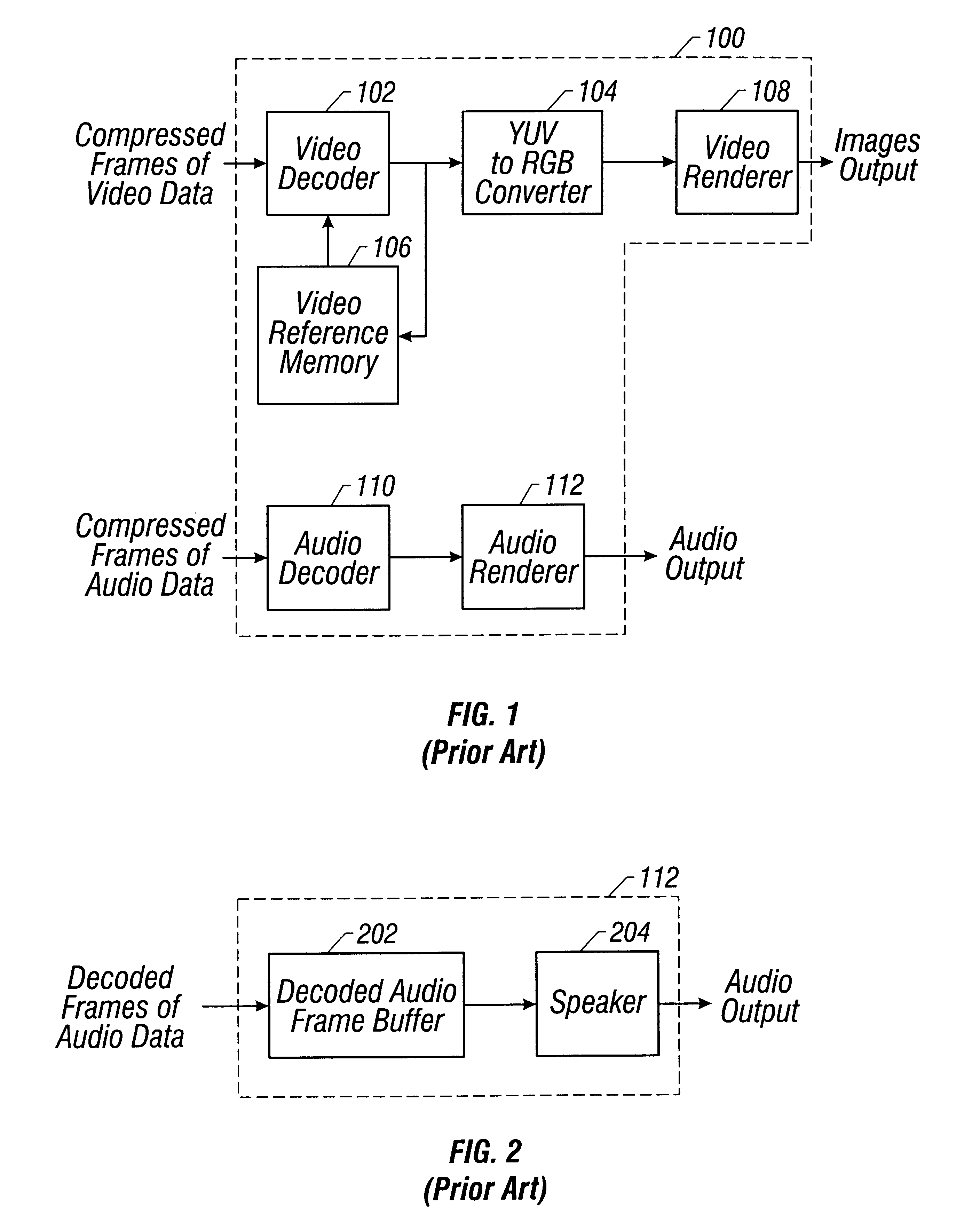
1. Field of the InventionThe present invention relates generally to audio and video decompression. More particularly, the present invention relates to a system and method for reducing audio breakups and other artifacts during audio and video decompression.2. Description of the Related ArtCompression and subsequent decompression of audio and video data has wide spread application. Applications include digital video transmission and digital television. In a typical digital video transmission, the participants transmit and receive audio and video signals that allow the participants to see and hear one another.To efficiently transmit the large amount of video and audio data generated at particular digital video transmission sites, digital video transmission systems typically digitize and compress the video and audio data for transmission across digital networks. Various compression schemes are available, and various digital networks are available as well.Decompression of audio and video...

Claims


Application Information

Patent Timeline
IPC IPC(8): H04N5/60H04N5/44
CPCG06F9/50H04N5/602Y02B60/142H04N5/4401H04N21/426Y02D10/00
Inventor WHITFORD, PAUL H.PARRY, JAMES H.TAN, SEE-MONG
Owner CISCO TECH INC
Learn More