Sand control method and apparatus

a technology of sand control and apparatus, applied in the field of wells, can solve the problems of reducing the production rate and damage of subsurface production equipment, affecting the operation of drinking water systems,

Inactive Publication Date: 2004-06-22
SCHLUMBERGER TECH CORP
View PDF32 Cites 48 Cited by
  • Summary
  • Abstract
  • Description
  • Claims
  • Application Information

AI Technical Summary

Benefits of technology

One embodiment of the present invention is a gravel pack system comprising a conduit having a plurality of outlets along its length, a delivery tubing extending to a well surface and a releasable connector releasably connecting the conduit to the delivery tubing. The conduit and the delivery tubing are in fluid communication. The conduit outlets can comprise perforations within the conduit, and can contain nozzles extending into the conduit. The conduit can also have baffle elements within its interior. The nozzles and baffle elements increase the pressure drop and turbulence that exists during a gravel pack operation and decrease the likelihood of gravel bridging within the conduit. To ease the drilling out of the conduit after the gravel pack operation is complete, the conduit can be made of an easily drillable material. It can also be made of a composite material.

Problems solved by technology

Sand or silt flowing into the wellbore from unconsolidated formations can lead to an accumulation of fill within the wellbore, reduced production rates and damage to subsurface production equipment.
Due to its highly abrasive nature, sand contained within production streams can result in the erosion of tubing, flowlines, valves and processing equipment.
The loss of material from the reservoir matrix can also lead to the movement and possible collapse of the reservoir.
The problems caused by sand production and the deterioration of the reservoir support matrix can significantly increase operational and maintenance expenses and can lead to a total loss of the well.
A problem that is frequently encountered in a sand control operation, especially in long or highly deviated sections or formations with high permeability, is the formation of gravel bridges within the wellbore.
Non-uniform gravel distribution within the wellbore often occurs as a result of the premature loss of carrier fluid from the slurry.
The fluid can be lost into high permeability zones within the formation, leading to the creation of gravel bridges in the wellbore, before all the gravel has been placed.
These gravel bridges will restrict the flow of slurry in the wellbore and result in voids within the completion zone needing sand control.
Voids within the sand control treatment allow formation sand and fines to be carried out of the reservoir matrix with the produced fluids and can lead to the problems mentioned above.
This multiple trip approach increases the time and expense of completing the well, and also increases the risk of encountering wellbore problems, such as losing tools or becoming stuck.
The nozzles and baffle elements increase the pressure drop and turbulence that exists during a gravel pack operation and decrease the likelihood of gravel bridging within the conduit.
FIG. 1 is a cross-sectional view of a well and illustrates a sand control operation resulting in a gravel bridge developing resulting in an incomplete treatment throughout the perforated zone.

Method used


Image

  • Sand control method and apparatus
  • Sand control method and apparatus
  • Sand control method and apparatus

Examples


Embodiment Construction

Illustrative embodiments of the invention are described below. In the interest of clarity, not all features of an actual implementation are described in this specification. It will of course be appreciated that in the development of any such actual embodiment, numerous implementation-specific decisions must be made to achieve the developers' specific goals, such as compliance with system-related and business-related constraints, which will vary from one implementation to another. Moreover, it will be appreciated that such a development effort might be complex and time-consuming, but would nevertheless be a routine undertaking for those of ordinary skill in the art having the benefit of this disclosure.

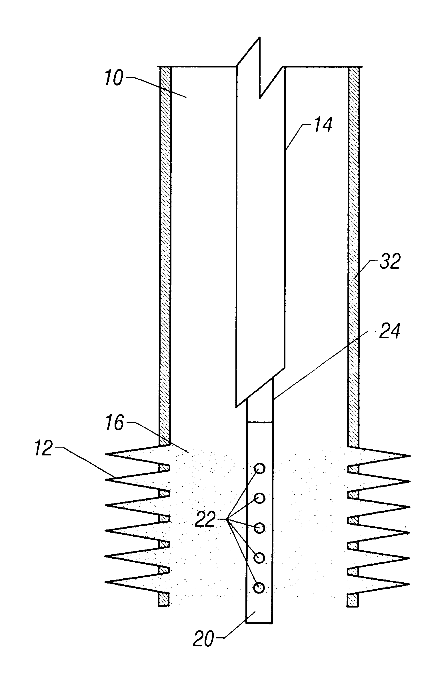
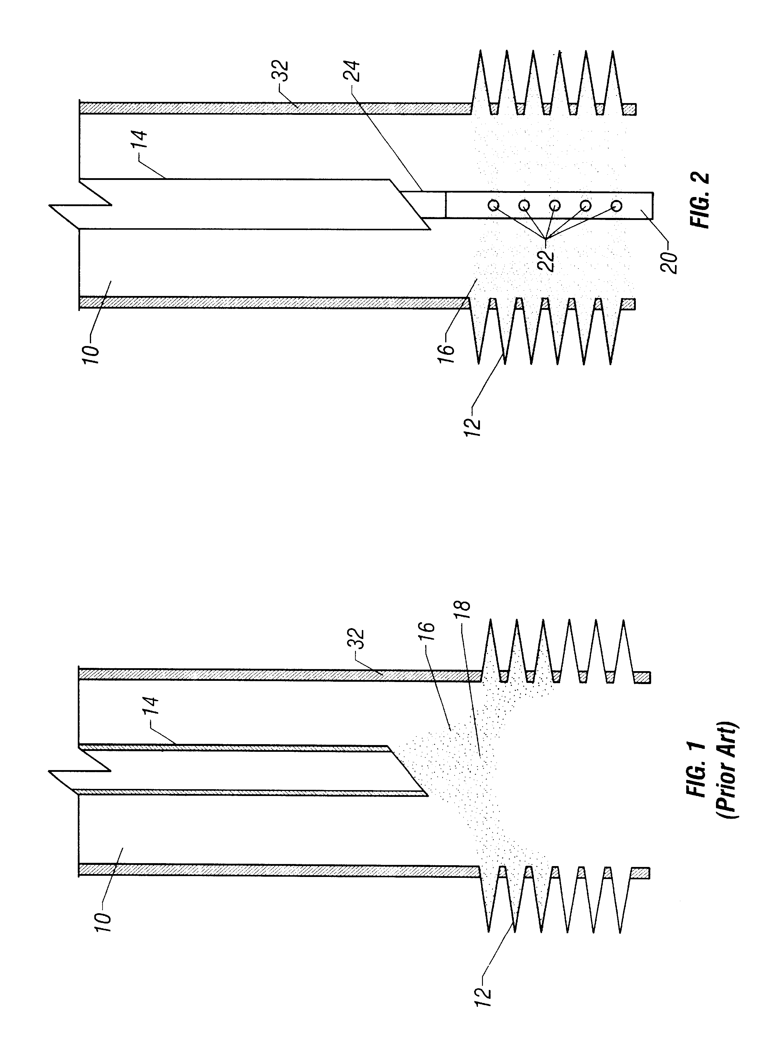
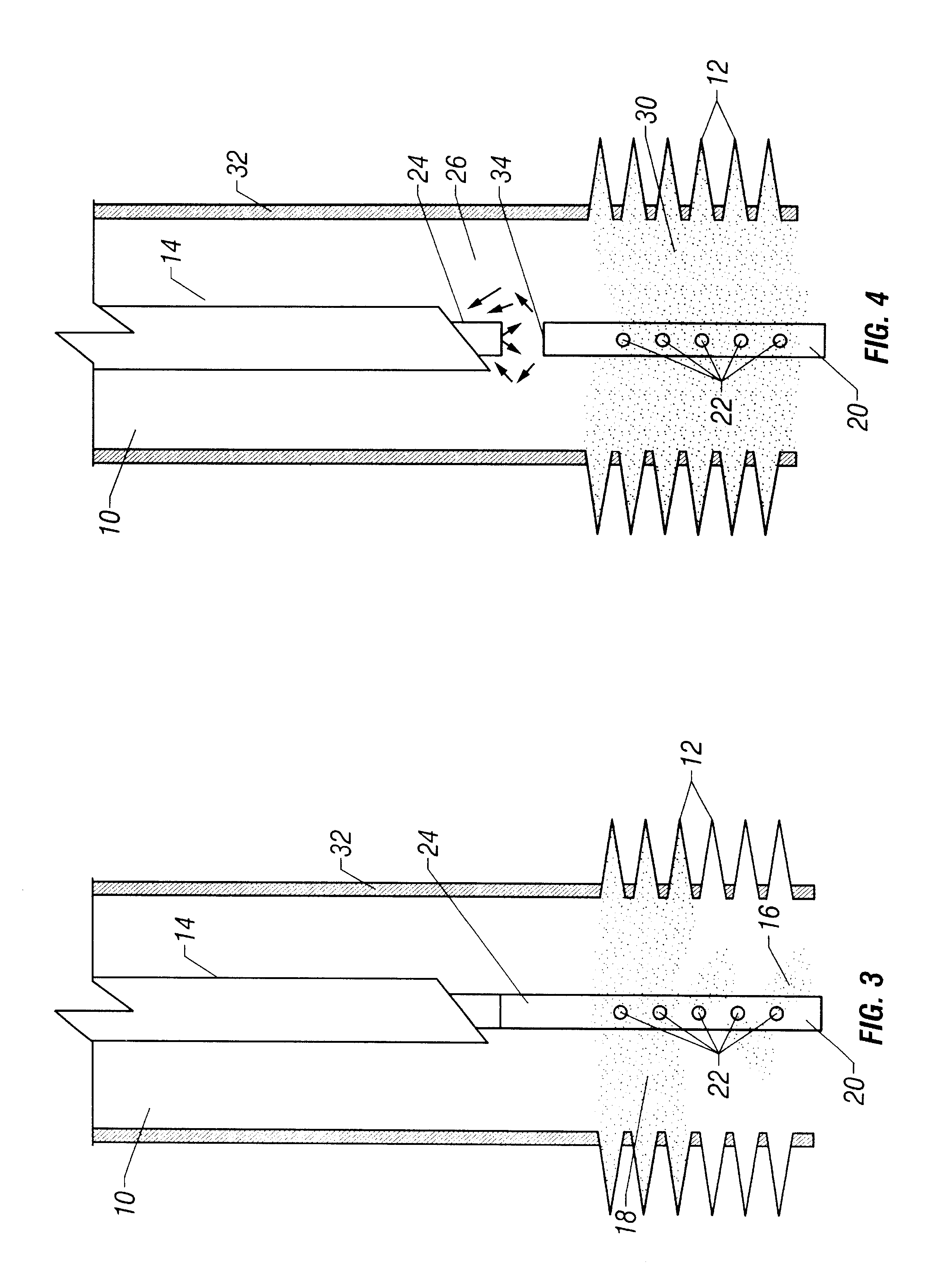
FIG. 1 illustrates a wellbore 10 having a plurality of perforations 12 through the well casing 32. A tubing string 14 is inserted into the wellbore 10 and placed above the perforations 12. A gravel slurry 16 is pumped down the tubing string where it enters the wellbore 10 and some of t...


PUM


Abstract

The present invention discloses a system using a conduit run into a well on a service string. In one embodiment the conduit includes outlets along its length to permit a sand control treatment to exit the conduit along the length of the conduit and distribute the sand control treatment along the length of the conduit. The conduit can have a plurality of such outlets spaced to provide an even distribution of the sand control treatment. The conduit can be attached to the delivery tubing (such as coiled tubing or service string tubing) via a releasable connector. The conduit is deployed on the delivery tubing and connector (and is in fluid communication therewith) in the well adjacent to an area to be treated. The sand control treatment is pumped into the well. Once the sand control treatment is complete, the releasable connector is released to disconnect the conduit from the delivery tubing and the delivery tubing is removed from the well.

Description

1. Field of the InventionThe present invention relates to the field of wells. More specifically, the invention relates to a device and method for providing sand control within a well.2. Description of Related ArtHydrocarbon fluids such as oil and natural gas are obtained from a subterranean geologic formation, referred to as a reservoir, by drilling a well that penetrates the hydrocarbon-bearing formation. Once a wellbore has been drilled, the well must be completed before hydrocarbons can be produced from the well. A completion involves the design, selection, and installation of equipment and materials in or around the wellbore for conveying, pumping, or controlling the production or injection of fluids. After the well has been completed, production of oil and gas can begin.Sand or silt flowing into the wellbore from unconsolidated formations can lead to an accumulation of fill within the wellbore, reduced production rates and damage to subsurface production equipment. Migrating sa...

Claims


Application Information

Patent Timeline
Patent Type & Authority Patents(United States)
IPC IPC(8): E21B43/02E21B43/04
CPCE21B43/04
Inventor WATSON, GRAHAMKERNICK, GEOFFREY R.PRICE-SMITH, COLIN J.PARLAR, MEHMET
Owner SCHLUMBERGER TECH CORP
Why Eureka
Try Eureka