Method and apparatus for reducing power consumption for power supplied by a voltage adapter

Inactive Publication Date: 2004-06-22
INT BUSINESS MASCH CORP
View PDF8 Cites 87 Cited by
  • Summary
  • Abstract
  • Description
  • Claims
  • Application Information

AI Technical Summary

Problems solved by technology

For example, a computer system load may have a malfunctioning battery, or there may be a short circuit on the output of the voltage adapter.

Method used


Image

  • Method and apparatus for reducing power consumption for power supplied by a voltage adapter
  • Method and apparatus for reducing power consumption for power supplied by a voltage adapter
  • Method and apparatus for reducing power consumption for power supplied by a voltage adapter

Examples


Embodiment Construction

The claims at the end of this application set out novel features which applicants believe are characteristic of the invention. The invention, a preferred mode of use, further objectives and advantages, will best be understood by reference to the following detailed description of an illustrative embodiment read in conjunction with the accompanying drawings.

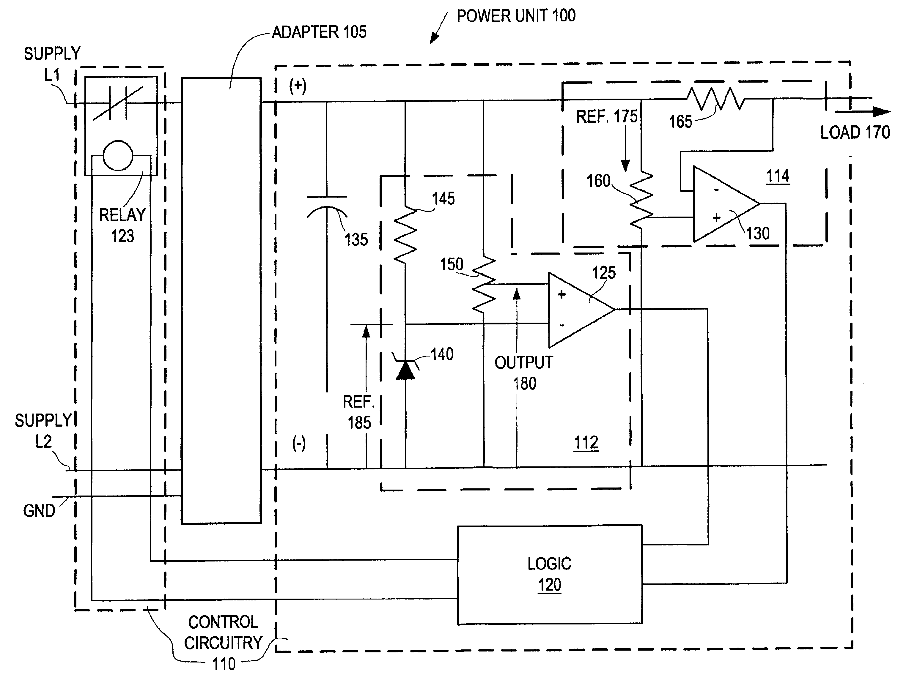
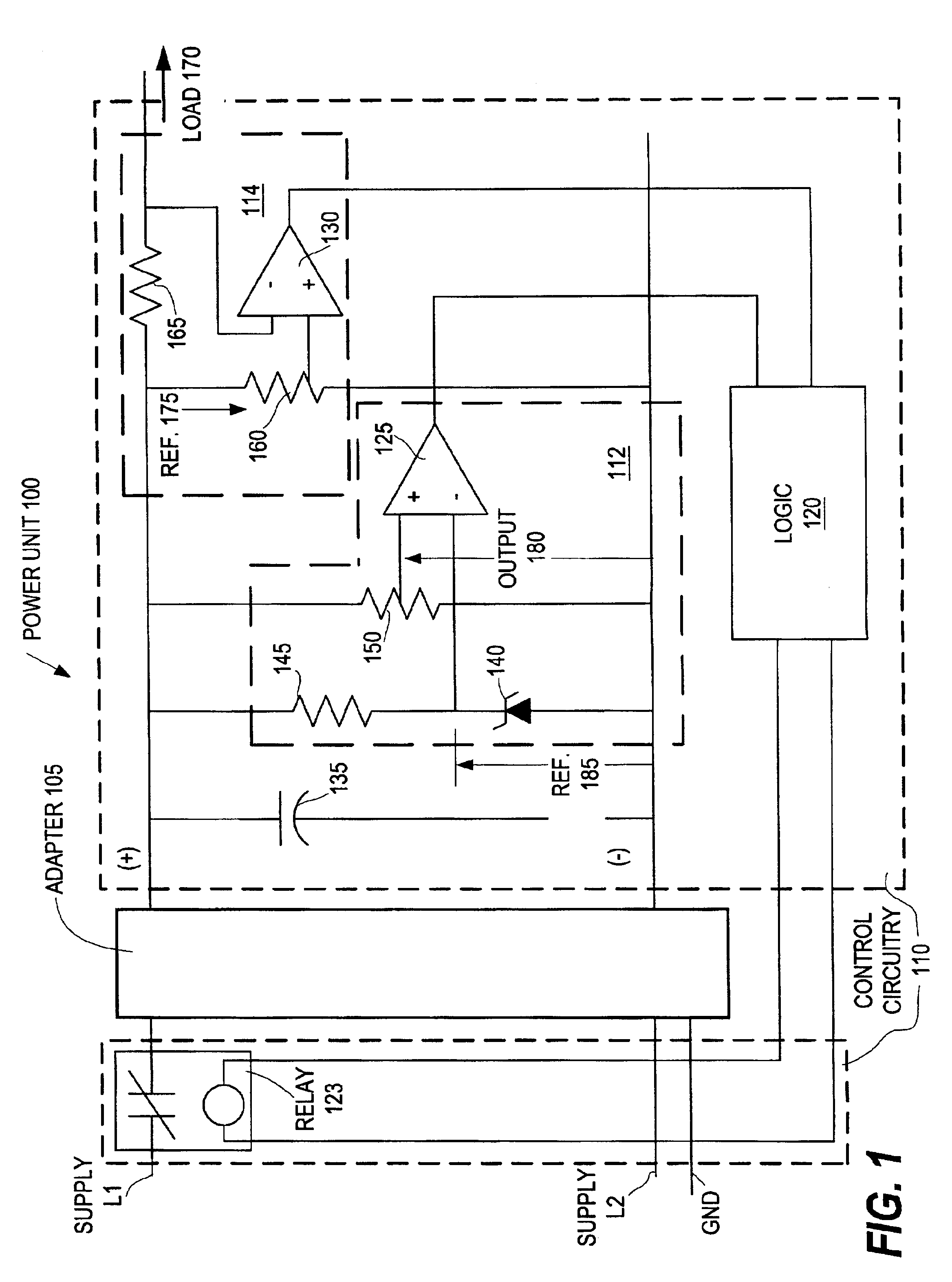
Referring now to FIG. 1, a power unit 100 is illustrated, according to an embodiment of the present invention. The power unit 100 includes a voltage adapter 105, which receives AC power from supply lines L1 and L2, and control circuitry 110, which monitors the adapter 105 and selectively disconnects one of the supply line from the adapter 105. The control circuitry 110 does this by measuring certain voltages and currents that are output by the adapter 105, inferring from these measurements, by logic 120, certain logical states, and energizing or de-energizing relay 123 responsively. Control relay 123 has normally closed contacts in...


PUM


Abstract

Power consumption is reduced for power supplied by a voltage adapter, such as an AC / DC adapter. A power source is connected to a power unit, including the voltage adapter and control circuitry. The voltage adapter supplies power to a load, such as a computer system. A load current supplied by the voltage adapter and an output voltage of the voltage adapter are measured by the control circuitry, and a control device of the control circuitry selectively disconnects the voltage adapter from the power source. The disconnecting is responsive to the control circuitry inferring from the measured current and voltage that the load is turned off, or at least operating in a reduced power consumption mode.

Description

1. Field of the InventionThis invention concerns supplying power to devices which utilize an AC to DC power supply or power adapter.2. Related ArtOn Jul. 31, 2001 the President of the United State issued the executive order, Energy Efficient Standby Power Devices. This executive order required that government agencies purchase equipment whose standby power is less then one Watt when possible. Australia is participating in the International Energy Agency's one Watt Program. The International Energy Agency has had three international workshops on standby power. Philips has programs, GreenChipTM and STARplugTM, that aim to reduce standby power and increase efficiency in power converters. ON Semiconductor has controllers for designing efficient wall adapters. This shows progress on making new devices with increased efficiency and reduced standby power, but legacy devices will continue to waste power until they have been phased out over a period of many years.It should therefore be appre...

Claims


Application Information

Patent Timeline
Patent Type & Authority Patents(United States)
IPC IPC(8): H02M5/00H02M5/42H02J3/00H02M7/04G06F1/26G06F1/28G06F1/32
CPCG06F1/263G06F1/28G06F1/3203H02M2001/0032Y02B70/16H02M1/0032Y02B70/10
Inventor MCDOWELL, CHANDLER TODDNASSIF, SANI RICHARD
Owner INT BUSINESS MASCH CORP
Why Eureka
Try Eureka