Gas exchange valve drive for a valve-controlled combustion engine

a technology of combustion engine and gas exchange valve, which is applied in the direction of machines/engines, non-mechanical valves, magnetic bodies, etc., can solve the problems of high noise level developing, high holding current, and abrupt braking

Inactive Publication Date: 2004-06-29
COMPACT DYNAMICS
View PDF12 Cites 18 Cited by
  • Summary
  • Abstract
  • Description
  • Claims
  • Application Information

AI Technical Summary

Benefits of technology

The concept on which the invention is based consists in spatially "removing" the portion of the stator which effects the armature magnetomotive force, i.e. the coil area with the stator coil, from the portion generating the force of the linear motor, i.e. the tooth area of the stator. Compared to conventional linear motors where the stator coils are arranged between two teeth each of the stator, a considerably higher magnetomotive force of the armature can be achieved. This is dues to the fact that the coil is subjected to considerably less spatial restrictions due to the inventive design and can therefore to optimized to minimal (ohmic) losses- and the associated maximal magnetic field induction. By the dimensions of the permanent-magnetic rings in the direction, of movement of the rotor or the dimensions of a tooth of the stator in the direction of movement of the rotor, respectively, a pole pitch is defined which is smaller than the dimension of the stator coil in its longitudinal direction.
Due to the high power density of the inventive arrangement the transverse dimensions (diameters) of the gas exchange valve with the required specifications can be kept very small. This allows the employment in compact passenger car engines.

Problems solved by technology

A considerable problem with the employment of an electromagnet arrangement for operating the valve is the high noise level developing upon reaching the respective end positions, the abrupt braking upon reaching the end positions, as well as the required high holding currents.
Here, the maximum speed of the engine, however, is considerably limited.
The start-up time upon starting is relatively long because of the required high force it takes some time for the valve arrangement to oscillate into its desired position.
These arrangements necessitate a very high manufacturing expenditure because the assembly of the coils around the individual teeth is difficult to realize.
Moreover, the pole pitch which can be achieved with this construction is relatively large.

Method used


Image

  • Gas exchange valve drive for a valve-controlled combustion engine
  • Gas exchange valve drive for a valve-controlled combustion engine
  • Gas exchange valve drive for a valve-controlled combustion engine

Examples


Embodiment Construction

Corresponding numerals in the figures identify identical parts or parts to the same effect, which are not repeatedly explained in the following.

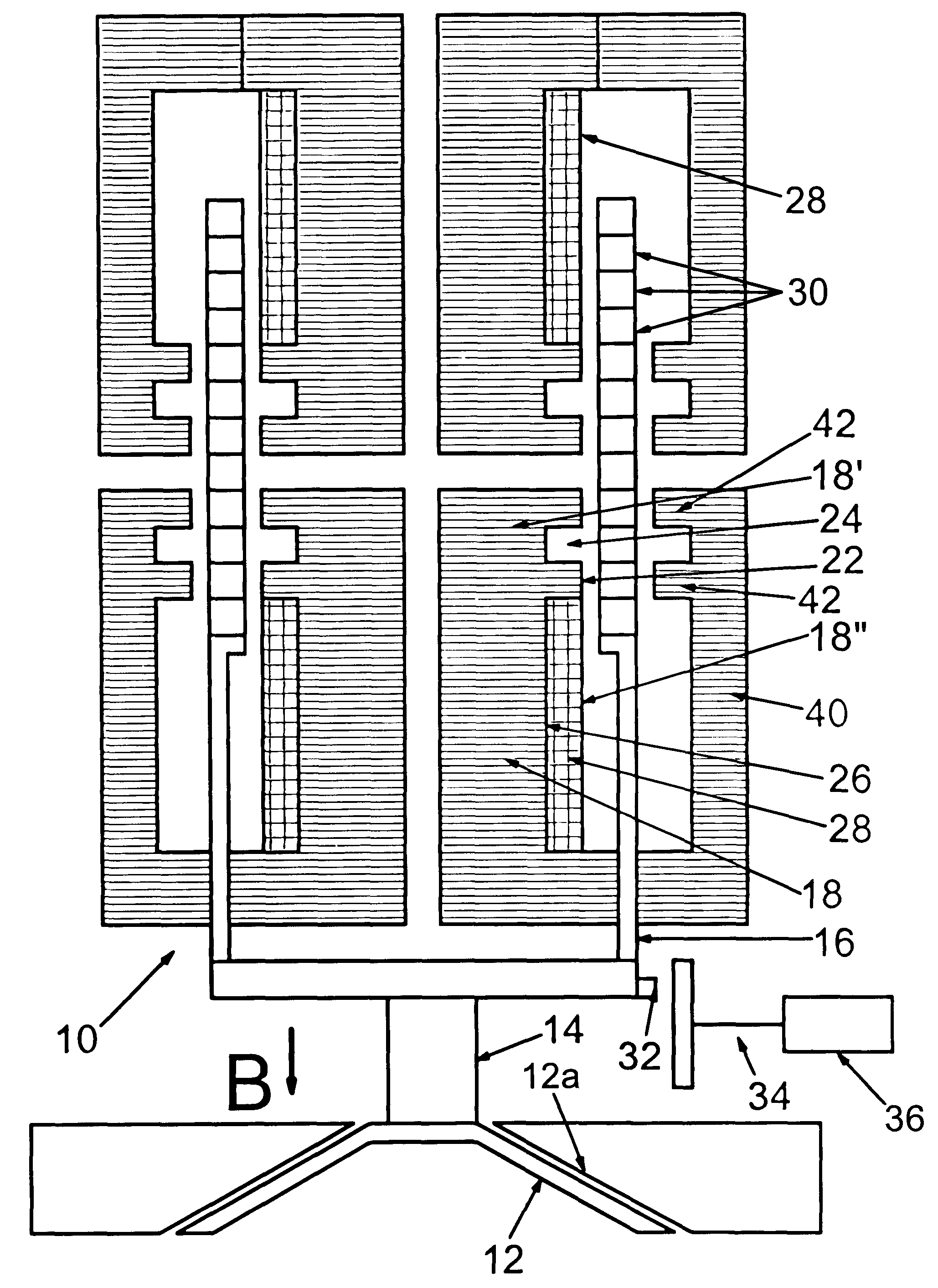
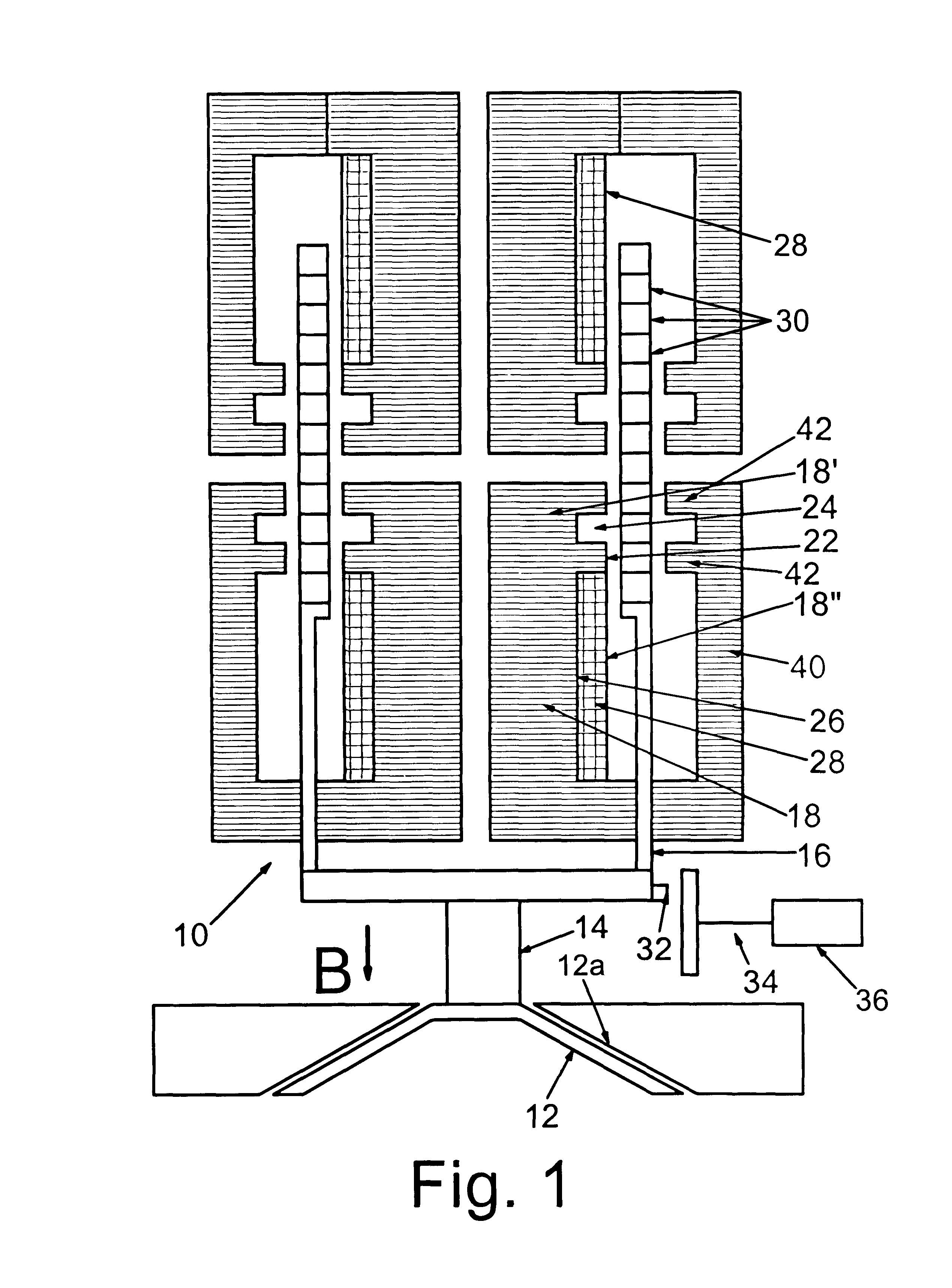
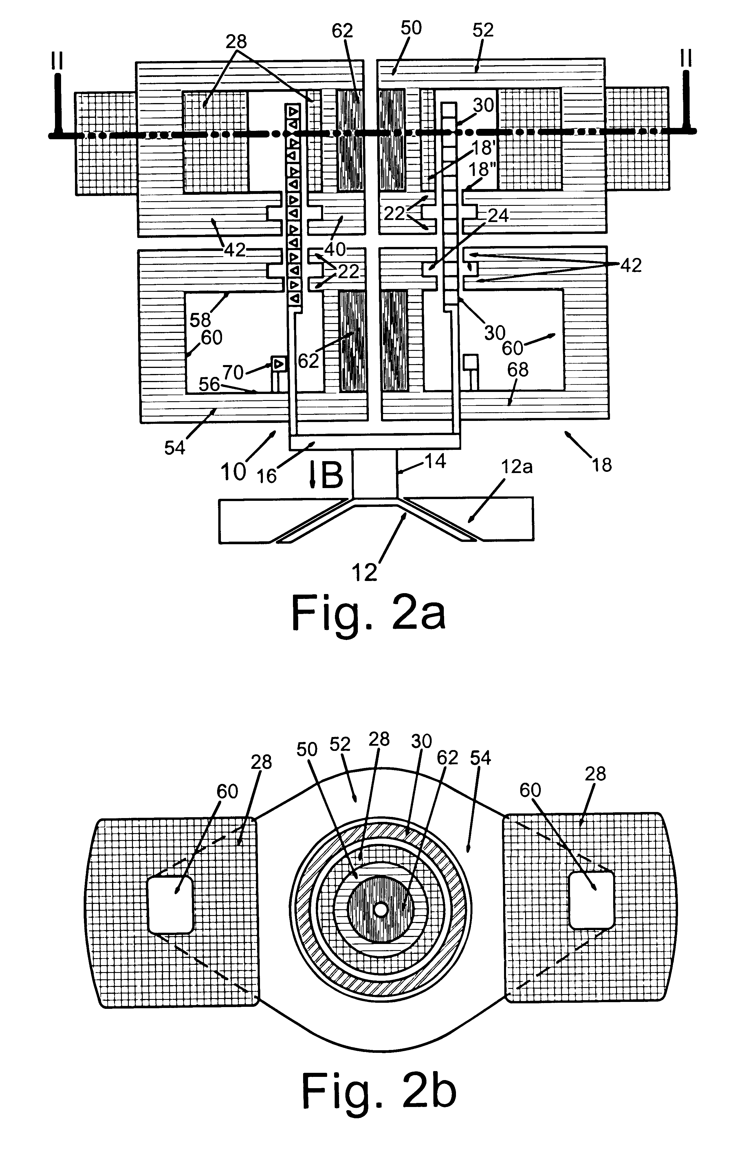
FIG. 1 illustrates a first embodiment of en electric linear motor 10 which, in the inventive valve arrangement, serves as an actuator for a valve member 12 of a gas exchange valve whose associated valve seat 12a is shown only schematically. The linear motor 10 has a rotor 16 coupled with the valve member 12 via a rod 14 and a stator 18.

The stator 18 in this embodiment is formed as a soft magnetic form body of an essentially hollow cylindrical shape and a core located therein from sintered iron metal powder. The form body is functionally divided into a tooth area 18' and a coil area 18" adjacent to the tooth area 18' but separated from same.

The tooth area 18' of the stator 18 has two teeth 22 in its circumference facing towards the rotor 16 with a closed lateral area. In the present example with the form bodies having a circular plan view, th...


PUM


Abstract

The present invention relates to a gas exchange valve drive for a valve-controlled combustion engine with a hollow cylindrical rotor (16) to be coupled with a valve member (12) and a stator (18), wherein the rotor (16) comprises permanent-magnetic rings (30) concentrically arranged one above the other, the stator (18) is at least partially constructed of a soft magnetic material and comprises at least one tooth (22) facing towards the rotor (16), the stator (18) comprises a radially inner magnetically conductive area (50) and a radially outer magnetically conductive area (52), with the rings (30) of the rotor (16) being arranged between the inner area (50) and the outer area (52) of the stator (18), and the outer area (52) of the stator (18) in at least one partial section (54) is designed with a C-shaped cross-section and comprises at least one stator coil (28).

Description

The present invention relates to a gas exchange valve drive for a valve-controlled combustion engine. In particular, the invention relates to a gas exchange valve where the reciprocating movement of the valve member is not effected and controlled by a cam shaft. Rather, the valve member is electrically actuated by the inventive gas exchange valve.STATE OF THE ARTFrom DE 195 18 056 A1 a gas valve control with a gas exchange valve is known, which is actuated by an electromagnet arrangement. By means of a special configuration of the pole shaft of the electromagnet arrangement, a signal related to the movement of the armature is generated in the control line of the electromagnet arrangement. This signal can be evaluated for detecting any armature position without additional sensors. A considerable problem with the employment of an electromagnet arrangement for operating the valve is the high noise level developing upon reaching the respective end positions, the abrupt braking upon reac...

Claims


Application Information

Patent Timeline
Patent Type & Authority Patents(United States)
IPC IPC(8): F01L3/20F01L3/00F01L9/04F01L1/46F01L9/20F16K31/08
CPCF01L3/20F01L9/04H02K41/031F01L2009/0405F01L2009/0426F01L2009/0448F01L2009/0469F01L2101/00F01L2301/00F01L2009/2105F01L2009/2126F01L2009/2148F01L2009/2169F01L9/20
Inventor GRUNDL, ANDREASHOFFMANN, BERNHARD
Owner COMPACT DYNAMICS
Why Eureka
Try Eureka