AI technical title is built by Patsnap AI team. It summarizes the technical point description of the patent document.
a technology of actuators and actuators, applied in the direction of mechanical equipment, machines/engines, non-mechanical valves, etc., can solve the problem of high production cost of arrangemen
Inactive Publication Date: 2008-11-20
COMPACT DYNAMICS
View PDF30 Cites 5 Cited by
Summary
Abstract
Description
Claims
Application Information
AI Technical Summary
This helps you quickly interpret patents by identifying the three key elements:
Problems solved by technology
Method used
Benefits of technology
Benefits of technology
[0014]Another concept on which the invention is based consists of “separating out” that part of the stator which effects the armature magnetomotive force, namely the coil area with the stator coil arrangement, spatially from the part which forms the force of the linear actuator, namely the toothed area of the stator. Thus, in comparison with traditional linear motors, in which the stator coils are each arranged between two teeth of the stator, a considerably higher armature magnetomotive force can be achieved. This is because the coil, because of the form according to the invention, has considerably fewer spatial restrictions, and can thus be optimised to minimum (ohmic) losses, and associated maximum magnetic flux induction. The arrangement of the stator coil arrangement, the central longitudinal axis of which is oriented transversely to the direction of motion of the rotor, or in other words is essentially aligned with the central longitudinal axis of two opposite teeth of a tooth pair, is magnetically specially efficient, because the magnetic flux which is induced by a coil in such an orientation flows equally through the tooth pairs on the two faces of the coil. Thus a corresponding force is generated in both stacks of permanently magnetic rods. With no other special steps, this prevents the rotor running skew.
[0017]Similarly, the rotor magnetic pole / stator tooth arrangements, which cause the force and movement, are concentrated, so that they are not interrupted by stator coil arrangements. This allows a very small pole pitch, which in turn causes a high force density. Additionally, with the arrangement according to the invention, partial liftings of the rotor are possible.
[0018]Another essential advantage of the linear actuator according to the invention is that practically only the magnetically active components (the permanent magnets) contribute to the inertmass of the rotor, whereas all other parts of the motor (coils, magnetic return path, etc.) are assigned to the stator. In this way, a specially high ratio of force exerted by the actuator to inertmass can be achieved.
[0019]Because of the arrangement (single-phase and hollow cylindrical, e.g. rectangular in cross-section), which can be simply formed, of the stator coil arrangements, it is possible to keep the effect of the jarring forces acting on the coil low, so that vibrations of the coil or friction of the coil on the wall of the stator coil chamber are small. It is thus possible to manage with minimum insulation material and lining material of the stator coil chamber. This too contributes to the compactness and reliability of the total arrangement. Additionally, the simple structure results in a high power density even in the case of small linear actuators, since the achievable fill factor of the stator coil chamber (coil volume in the stator coil chamber relative to the total volume of the stator coil chamber) is high.
[0027]According to the invention, in each case, two adjacent permanently magnetic rods of the two stacks of the rotor can be connected to each other by magnetically inactive spacers, at a predetermined distance. These spacers can contain a magnetically inactive light material (aluminium, titanium, plastic—also with glass fibre or carbon fibre inclusions—or similar). In this way the inertmass of the rotor is low, but its stability is high.
Problems solved by technology
These arrangements require very high expenditure in production, since the mounting of the coils around the individual teeth is difficult to implement.
Method used
Image
Click on the blue label to locate the original text in one second.
Reading with bidirectional positioning of images and text.
Examples
first embodiment
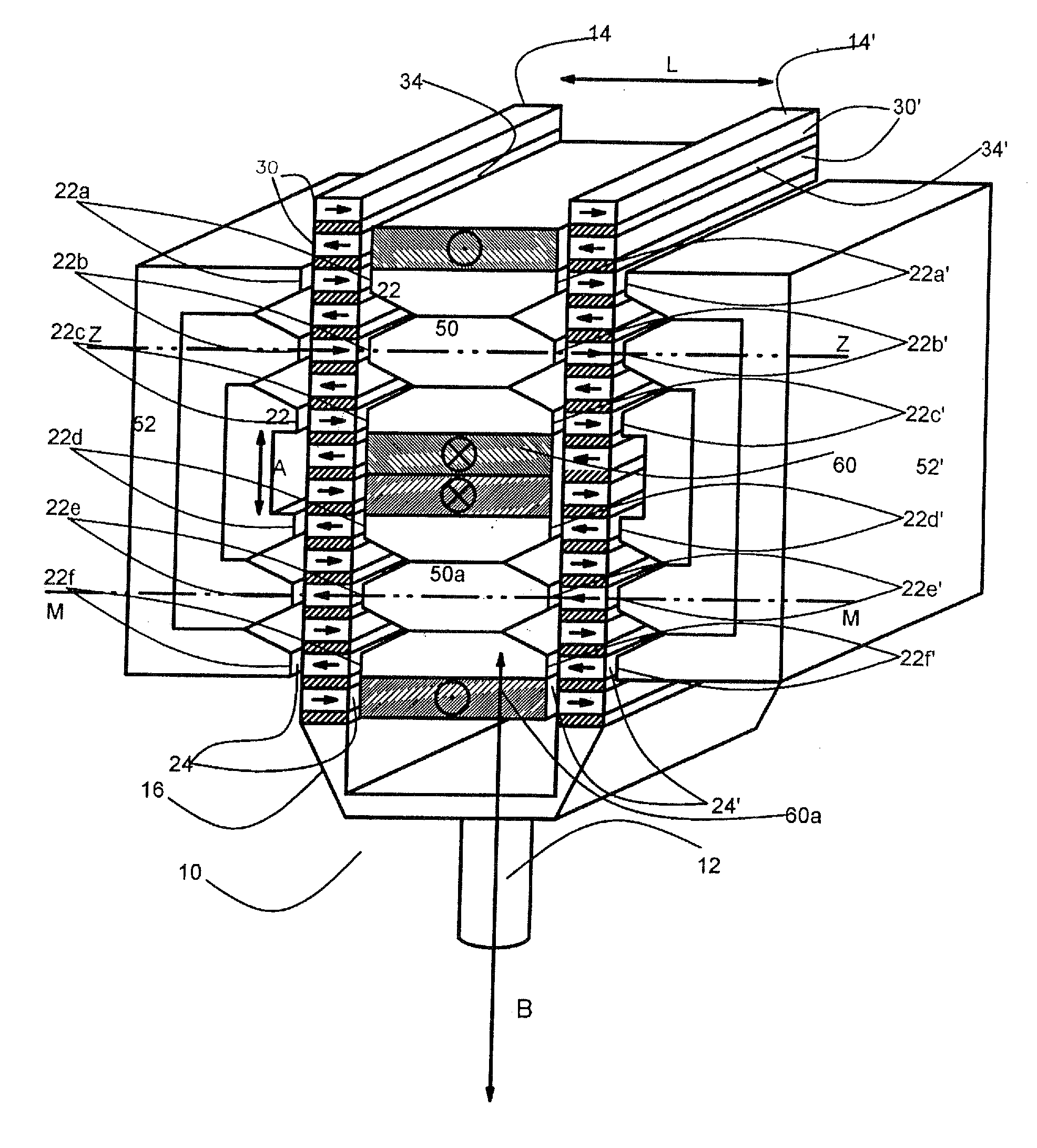
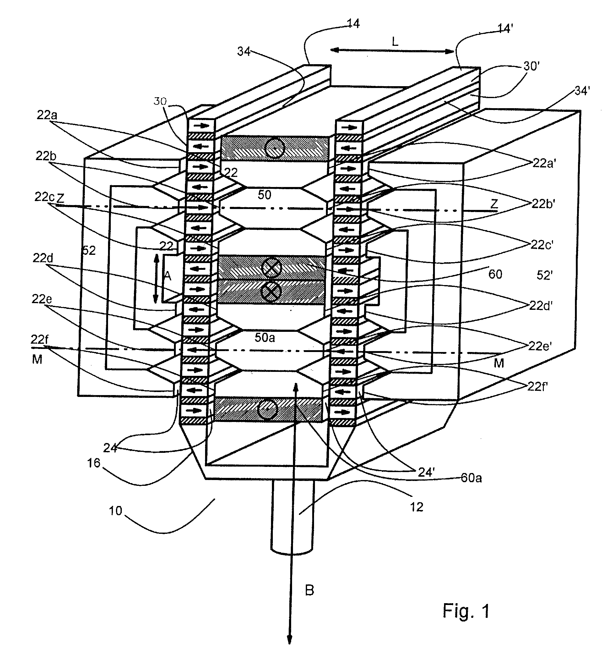
[0040]In FIG. 1, an electrical linear actuator 10, which has a rotor 16 and a stator 18 which are connected via a rod 12a to a part (not illustrated) to be driven, is illustrated.
[0041]The rotor 16 has two parallel stacks 14, 14′, which are arranged at a distance L from each other, of multiple permanently magnetic rods 30, 30′, which are of essentially cuboidal shape and arranged one above another.
[0042]The stator 18 is in the form of a soft magnetic mould of sintered ferrousmetalpowder or layered iron sheets. The stator 18 has multiple tooth pairs 22a, 22a′; 22b, 22b′; 22c, 22c′; 22d, 22d′; 22e, 22e′; 22f, 22f′ with teeth 22 opposite each other. Between the teeth 22 of each tooth pair, one of the two stacks 14, 14′ is received, forming an air gap 24 and 24′ respectively.
[0043]Between the two stacks 14, 14′ of the rotor 16, the stator 18 has magnetically conducting inner areas 50, 50a, which are arranged at a predetermined distance A from each other in the direction of motion B of...
second embodiment
[0051]In FIG. 5, an electrical linear motor 10 is illustrated. The reference symbols which are used in the previous figures designate parts or components with the same or comparable function or method of working, and are therefore explained below only to the extent that their tangible form, function or method of working differs from what is described above.
[0052]In the case of this embodiment, the rotor 16 has a stack 14 of multiple permanently magnetic rods 30, which arranged one above another and of essentially cuboidal shape. The stator 18 is in the form of a soft magnetic sheet metal packet stack. The stator 18 has multiple tooth pairs 22a . . . 22f with mutually opposite teeth 22. Between the teeth 22 of a tooth pair, the stack 14 is received, forming an air gap 24 and 24′ respectively.
[0053]On one side of the stack 14 of the rotor 16 (on the right-hand side in FIG. 5), the stator 18 has two magnetically conducting inner areas 50, 50a, which in the direction of motion B of the ...
PUM
Abstract
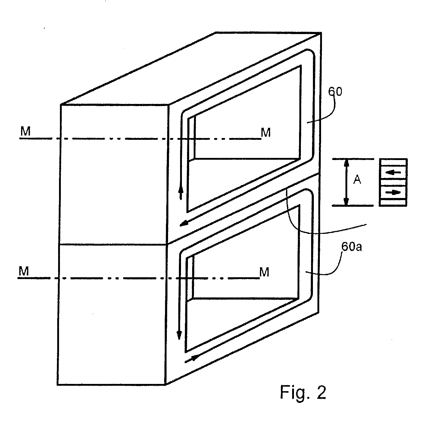
A linear actuator is provided with a rotor and a stator. The rotor comprises at least two stacks of permanently magnetic rods one over another, the stacks being arranged at a predetermined distance from each other. The stator is at least partly produced from a soft magnetic material, and comprises at least two pairs of teeth with teeth opposite each other, each pair of teeth receiving one of the two stacks between them while forming an air gap. The stator has at least two magnetically conducting inner areas which are located between the two stacks and arranged at a predetermined distance from each other in the direction of motion of the rotor. The inner areas are each at least partially surrounded by a substantially hollow cylindrical coil arrangement, the central longitudinal axis of which is oriented substantially transversely to the direction of motion of the rotor.
Description
BACKGROUND OF THE INVENTION[0001]This invention concerns a linear actuator, which is to be operated electrically, with a rotor and a stator, the rotor being set up to act on an element which is to be moved.PRIOR ART[0002]From JP-A-3-92518, a drive device is known, the stator in said drive device being constructed of two approximately semi-cylindrical shells, which both in the circumferential direction and in the longitudinal direction of each shell have divided teeth which face the rotor. The individual teeth of each shell are each surrounded by a coil, the central longitudinal axis of which runs in the radial direction. The result is a magnetic flux which is oriented in the radial direction, and which, starting from each one of the multiple teeth, flows into the rotor through the air gap between stator and rotor.[0003]A version, which agrees to this extent, of the stator, stator coils and rotor of a drive device for a valve arrangement in internal combustion engines is described in...
Claims
Application Information
Patent Timeline
Application Date:The date an application was filed.
Publication Date:The date a patent or application was officially published.
First Publication Date:The earliest publication date of a patent with the same application number.
Issue Date:Publication date of the patent grant document.
PCT Entry Date:The Entry date of PCT National Phase.
Estimated Expiry Date:The statutory expiry date of a patent right according to the Patent Law, and it is the longest term of protection that the patent right can achieve without the termination of the patent right due to other reasons(Term extension factor has been taken into account ).
Invalid Date:Actual expiry date is based on effective date or publication date of legal transaction data of invalid patent.
Patent Type & AuthorityApplications(United States)

