Digital VTR

a digital and time-varying technology, applied in the field of digital time-varying technology, can solve the problems of inability to realize a linear time-varying function, inability to record control signals such as information relating, and inability to record control signals on video tap

a digital and time-varying technology, applied in the field of digital time-varying technology, can solve the problems of inability to realize a linear time-varying function, inability to record control signals such as information relating, and inability to record control signals on video tap

US6766105B1Inactive Publication Date: 2004-07-20SANYO ELECTRIC CO LTD

Image

  • Digital VTR
  • Digital VTR
  • Digital VTR

Examples


first embodiment

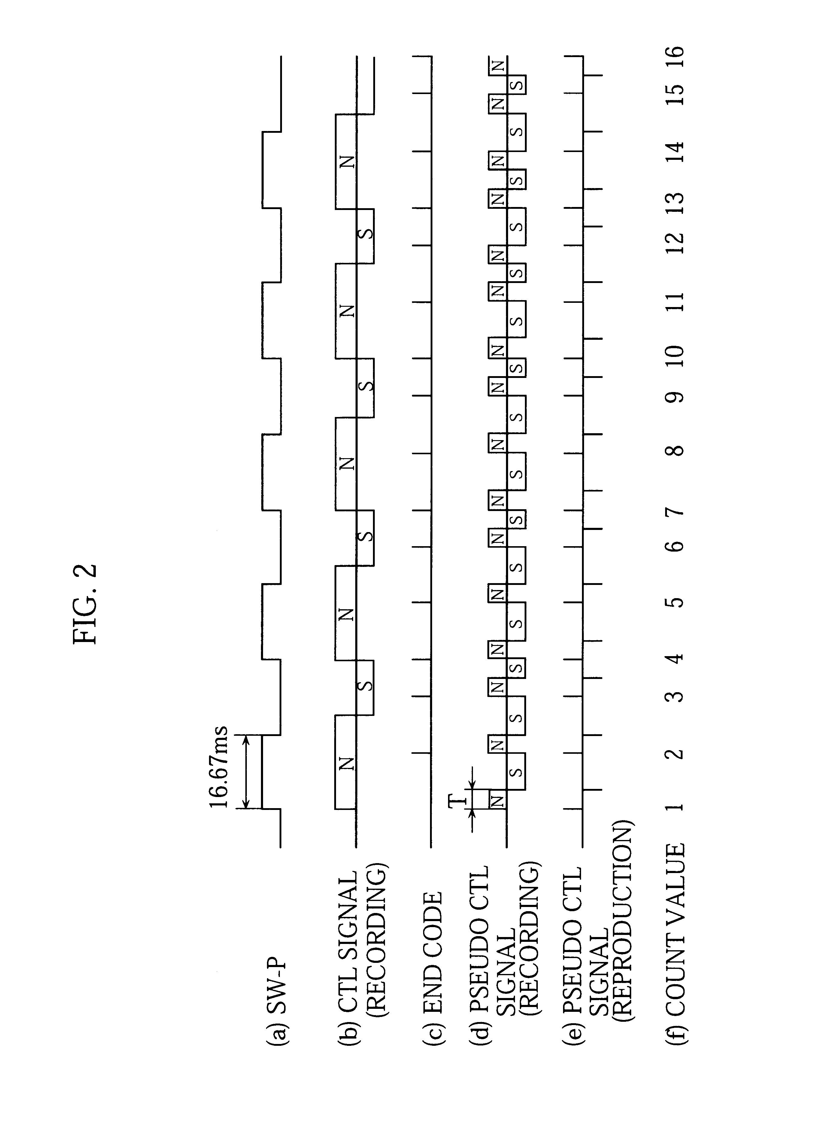
Referring now to FIGS. 1 and 2, the present invention will be described.

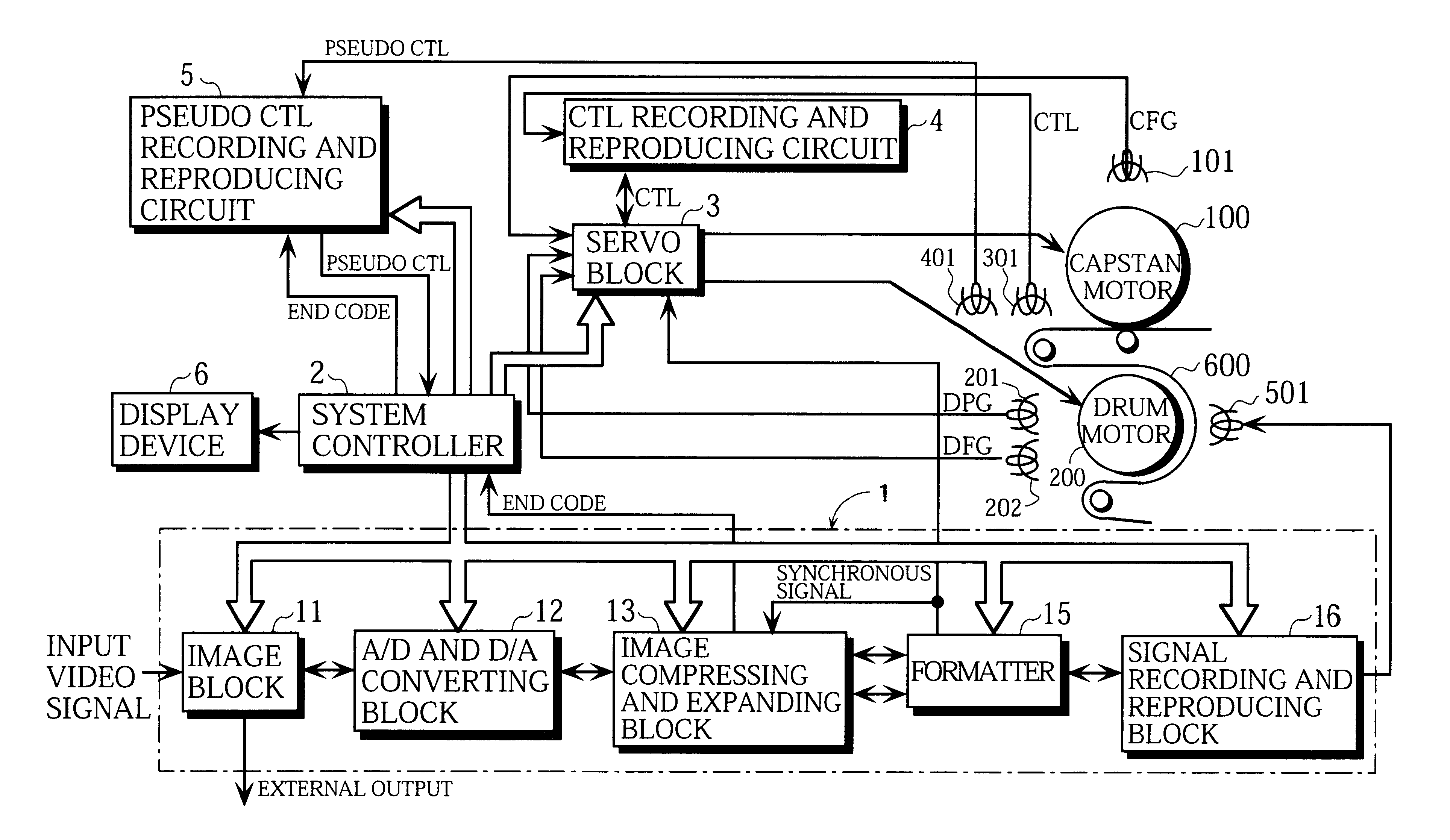
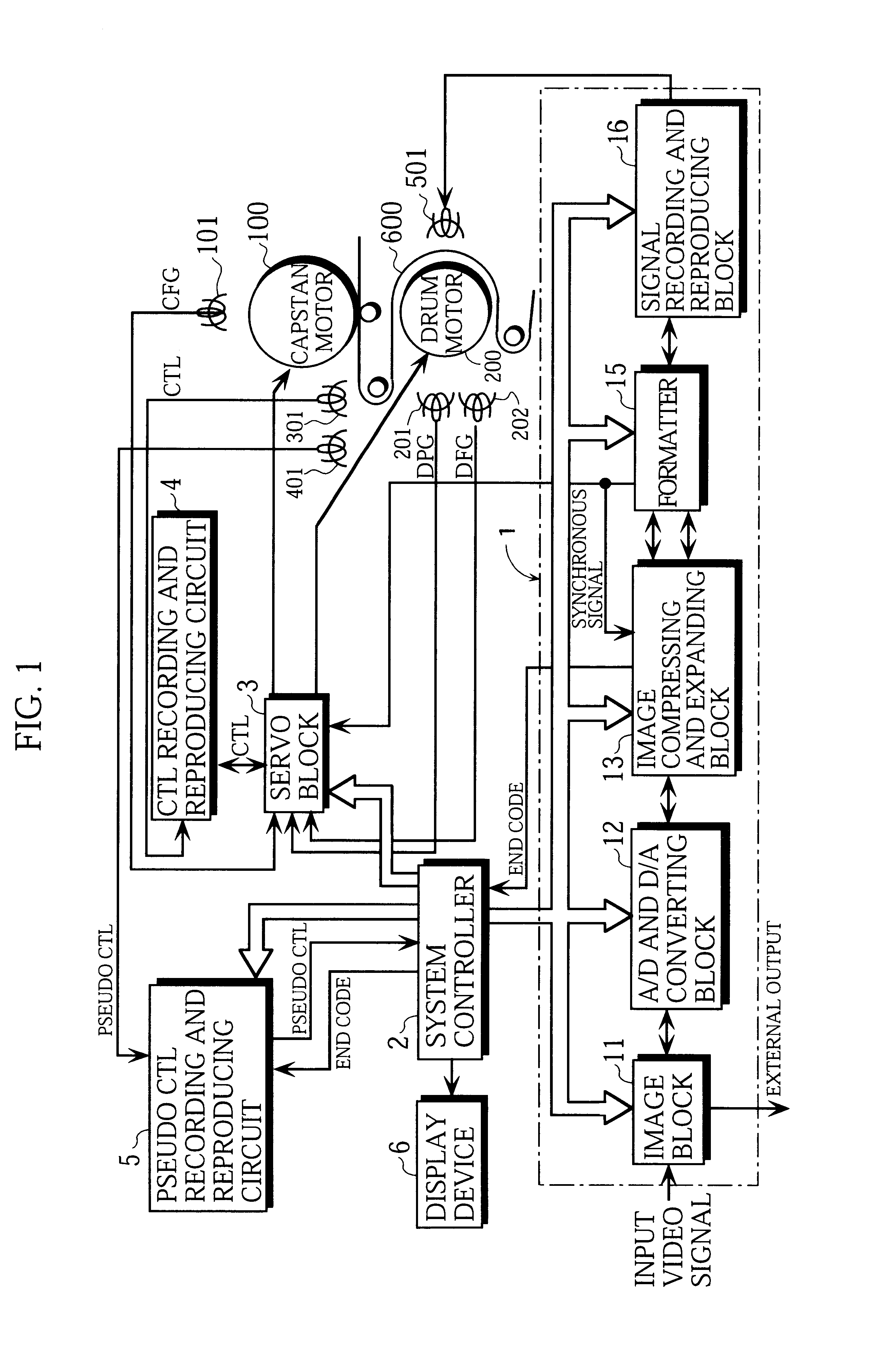
FIG. 1 illustrates the configuration of a digital VTR. In FIG. 1, a voice recording and reproducing unit is omitted.

The digital VTR comprises an image recording and reproducing unit 1, a system controller 2, a servo block 3, a CTL recording and reproducing circuit 4, a pseudo CTL recording and reproducing circuit 5, a display device 6, and so forth.

The servo block 3 controls a capstan motor 100 on the basis of an output of a capstan frequency generator (CFG) 101, a CTL signal, and the like, and controls a drum motor 200 on the basis of an output of a drum phase generator (DFG) 201, an output of a drum frequency generator (DFG) 202, and the like, as is well known.

The CTL recording and reproducing circuit 4 records the CTL signal on a control track of a video tape 600 using a CTL head 301 at the time recording, while reading out the CTL signal from the control track of the video tape 600 using the CTL head 301 at ...

second embodiment

[2] Description of Second Embodiment

Referring now to FIGS. 3 and 4, a second embodiment of the present invention will be described.

FIG. 3 illustrates the configuration of a digital VTR. In FIG. 3, a voice recording and reproducing unit is omitted.

The digital VTR comprises an image recording and reproducing unit 1, a system controller 2, a servo block 3, a CTL recording and reproducing circuit 4, a pseudo CTL recording and reproducing circuit 5, and so forth.

The servo block 3 controls a capstan motor 100 on the basis of an output of a capstan frequency generator (CFG) 101, a CTL signal, and the like, and controls a drum motor 200 on the basis of an output of a drum phase generator (DPG) 201, an output of a drum frequency generator (DFG) 202, and the like, as is well known.

The CTL recording and reproducing circuit 4 records the CTL signal on a control track of a video tape 600 using a CTL head 301 at the time recording, while reading out the CTL signal from the control track of the vi...


PUM


Abstract

A digital VTR according to the present invention comprises an image compressing circuit for subjecting input image data to variable length compression, to output variable length coding data and identification data representing the end of one field, recording means for recording on a video tape the variable length coding data outputted from the image compressing circuit, and pseudo CTL signal recording means for recording a pseudo CTL signal on the video tape every time the identification data is outputted from the image compressing circuit.

Description

1. Field of the InventionThe present invention relates to a digital VTR for subjecting input image data to variable length compression to record variable length coding data on a video tape so that the number of fields and the number of tracks composing the recorded variable length coding data are not in a linear relationship.2. Description of the Related ArtIn a digital VTR (Video Tape Recorder) comprising a conventional image compressing circuit, input image data is subjected to fixed length compression, and coding data obtained is recorded on a video tape, so that the number of fields and the number of tracks composing the recorded coding data are in a linear relationship. In such a digital VTR, the tape running distance obtained from CTL (control) pulses and the number of fields composing an image read out of the video tape are in a linear relationship, thereby making it possible to realize a linear time counter function in which absolute time information or the like is obtained ...

Claims


Application Information

Patent Timeline
20 Jul 2004
Publication
US6766105B1
IPC
H04N7/26; G11B27/10; G11B27/32; H04N5/926
CPC
G11B27/107; G11B27/324; H04N5/9261; H04N5/9268; G11B2220/91
Inventors
OKUTANI, AYUMU; SUGIMURA, YUKIO