Remotely programmable control device for use in electroluminescent display and lighting applications

a technology of electroluminescent display and remote programmable control, which is applied in the direction of electric digital data processing, instruments, computing, etc., can solve the problems of difficult modification of these devices, significant cost to replace the microprocessor, and process time and effor

Inactive Publication Date: 2004-08-03
IGRAPHICS
View PDF15 Cites 32 Cited by
  • Summary
  • Abstract
  • Description
  • Claims
  • Application Information

AI Technical Summary

Problems solved by technology

The microprocessor is the heart of the controller, and since it is very difficult to easily modify this electronic part, the controller is therefore relegated to a single purpose or a one-time use.
There are several known problems with controllers that use the architecture described above.
First, since it is difficult to modify these devices, they tend to be dedicated to a single display device.
This process requires time and effort, and carries a significant cost to replace the microprocessor.
Since it is very difficult to

Method used


Image

  • Remotely programmable control device for use in electroluminescent display and lighting applications
  • Remotely programmable control device for use in electroluminescent display and lighting applications
  • Remotely programmable control device for use in electroluminescent display and lighting applications

Examples


Embodiment Construction

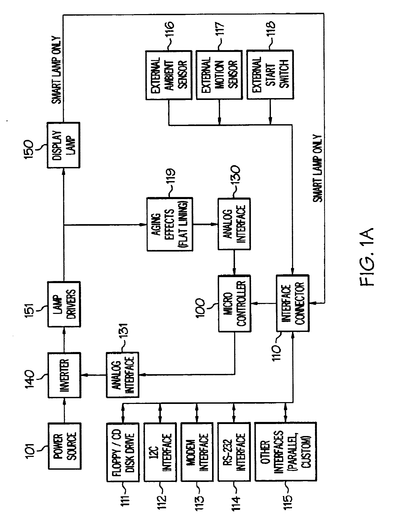
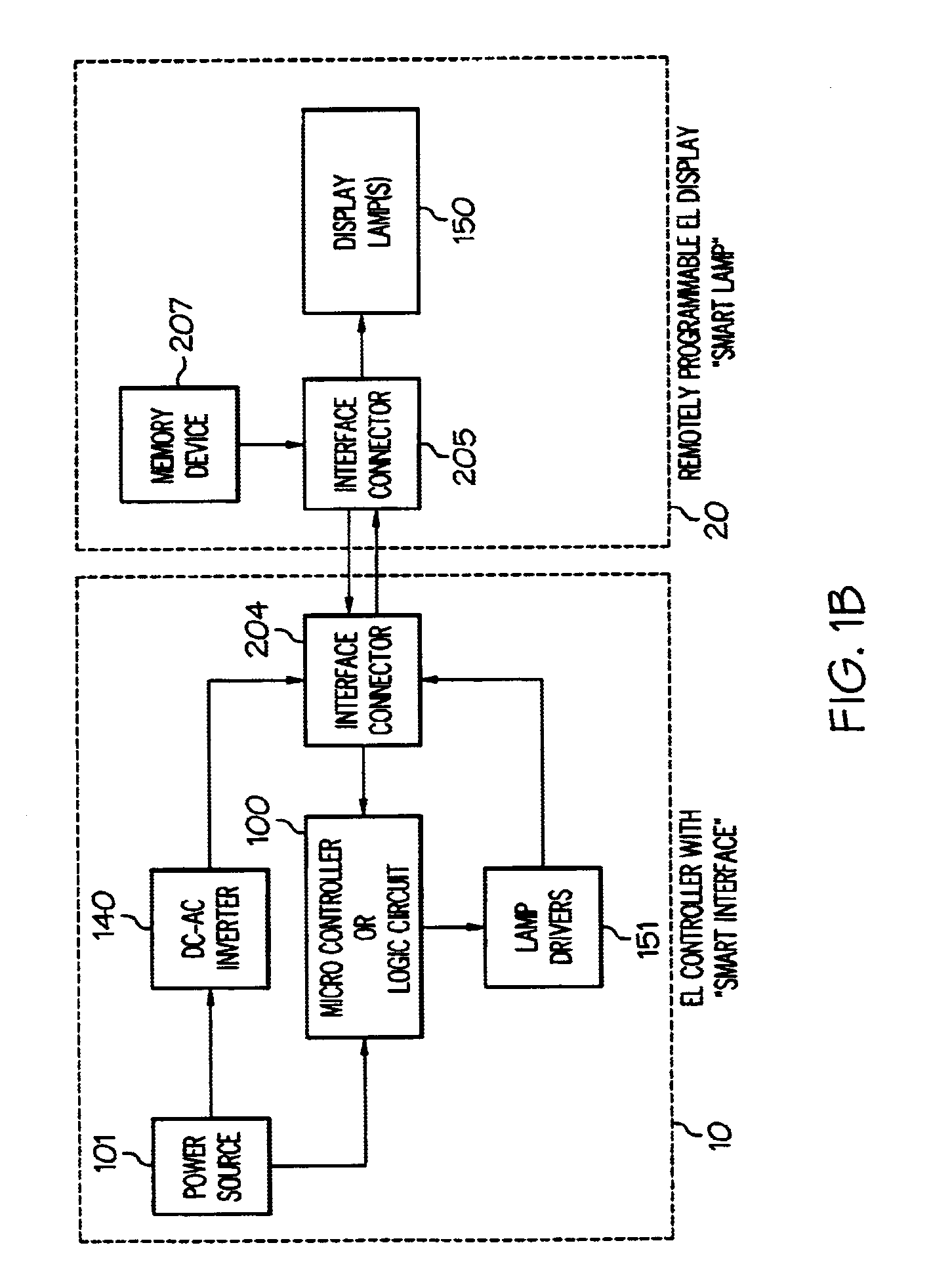
In one embodiment of the present invention, the controller 10 comprises or consists of a motherboard, a power supply, and various inverters and waveform conditioners. The controller 10 may also include inbound / outbound communications facilities, motion sensing apparatus, ambient lighting detection, scanning / flatlining techniques, a floppy disk reader and internal storage devices.

In an embodiment of the invention in which the controller 10 uses flatlining techniques the controller 10 includes a photosensor or other means for determining the lamp brightness.

The photosensor is positioned to monitor the brightness of the electroluminescent lamp. Should the lamp brightness diminish to a certain extent or to a particular brightness the lamp voltage is increased to maintain brightness over time. The flatlining techniques can be implemented by providing electronic sensing circuits which monitor the electroluminescent cells of the lamp and make adjustments to compensate for variations in the...


PUM


Abstract

Described is a remotely programmable control device for use in electroluminescent display and lighting applications. Elements of this invention include a power supply, various inverters/wave form conditioners, a motherboard, inbound/outbound communications capability, motion-sensing devices, ambient light sensing facilities, and a floppy disk reader. Remote programmability is achieved through several methods including detecting the driving instructions from the lamp display itself, or downloading data from a remote network or a floppy disk.

Description

1. Field of the InventionThe present invention relates to controllers for electroluminescent display and lighting systems. More particularly, the present invention relates to remotely programmable controllers for electroluminescent display and lighting systems.2. Description of the Related ArtElectroluminescent display and lighting systems are presently known. A typical electroluminescent display system combines one or more electroluminescent lamps or other electroluminescent display elements with an electronic driver or controller. Often various graphical or artistic elements such as overlays are laminated onto the lamps. These systems can resemble circuits in that the display elements are segmented into various areas that are independently addressable. Power and wave form is delivered to the display elements by an electronic driver which also delivers display control through a series of electronic impulses that are sent through one or many channels that act as wiring for the circu...

Claims


Application Information

Patent Timeline
IPC IPC(8): G09G5/00G09G3/30
CPCG09G3/30G09G2320/043G09G2320/0626G09G2360/144
Inventor ABRAHAM, JOHN M.HAYNES, BRYAN D.WILKINSON, MATTHEWMUSAL, MARK
Owner IGRAPHICS
Why Eureka
Try Eureka