System for specifying core voltage for a microprocessor by selectively outputting one of a first, fixed and a second, variable voltage control settings from the microprocessor

a microprocessor and core voltage technology, applied in the direction of liquid/fluent solid measurement, instruments, semiconductor/solid-state device details, etc., can solve the problems of microprocessor utilization, low supply voltage that can achieve the rated clock speed, additional power consumption and additional hea

Inactive Publication Date: 2004-08-03
ADVANCED SILICON TECH +1
View PDF45 Cites 133 Cited by
  • Summary
  • Abstract
  • Description
  • Claims
  • Application Information

AI Technical Summary

Problems solved by technology

For example, while higher clock speeds are generally desirable, a higher clock speed requires a higher supply voltage, which results in additional power consumption and additional heat, which needs to be dissipated.
Microprocessors utilized in mobile applications are particularly sensitive to power dissipation and generally require the lowest power dissipation and thus require the lowest supply voltage that can achieve the rated clock speed.
However, that approach provides no guarantee that appropriate voltage and frequency settings will be utilized.
In fact, certain unscrupulous suppliers of computer systems have been known to provide systems having higher than recommended voltages and frequencies.
Since companies typically qualify chips at certain voltage and frequencies, such over clocking or excessive voltage can result in shorter product lifetimes, decreased reliability and excessive product returns.
Providing information to users, which specifies the correct voltage and hoping that the correct voltage is subsequently supplied to the processor by circuitry on the board, as illustrated in FIG. 1, is subject both to intentional misuse and unintentional mistake.
In addition, the more possible voltage settings that exist, the greater the possibility for error.
But there is no easy mechanism in place for software to determine the appropriate core voltage corresponding to a maximum frequency rating for a specific processor.

Method used


Image

  • System for specifying core voltage for a microprocessor by selectively outputting one of a first, fixed and a second, variable voltage control settings from the microprocessor
  • System for specifying core voltage for a microprocessor by selectively outputting one of a first, fixed and a second, variable voltage control settings from the microprocessor
  • System for specifying core voltage for a microprocessor by selectively outputting one of a first, fixed and a second, variable voltage control settings from the microprocessor

Examples


Embodiment Construction

)

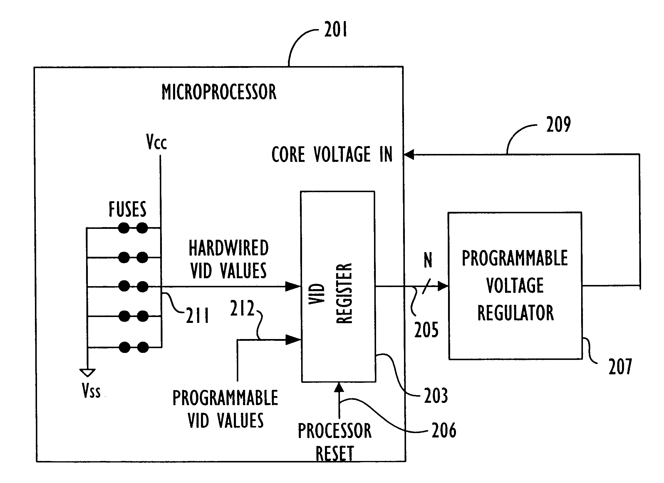
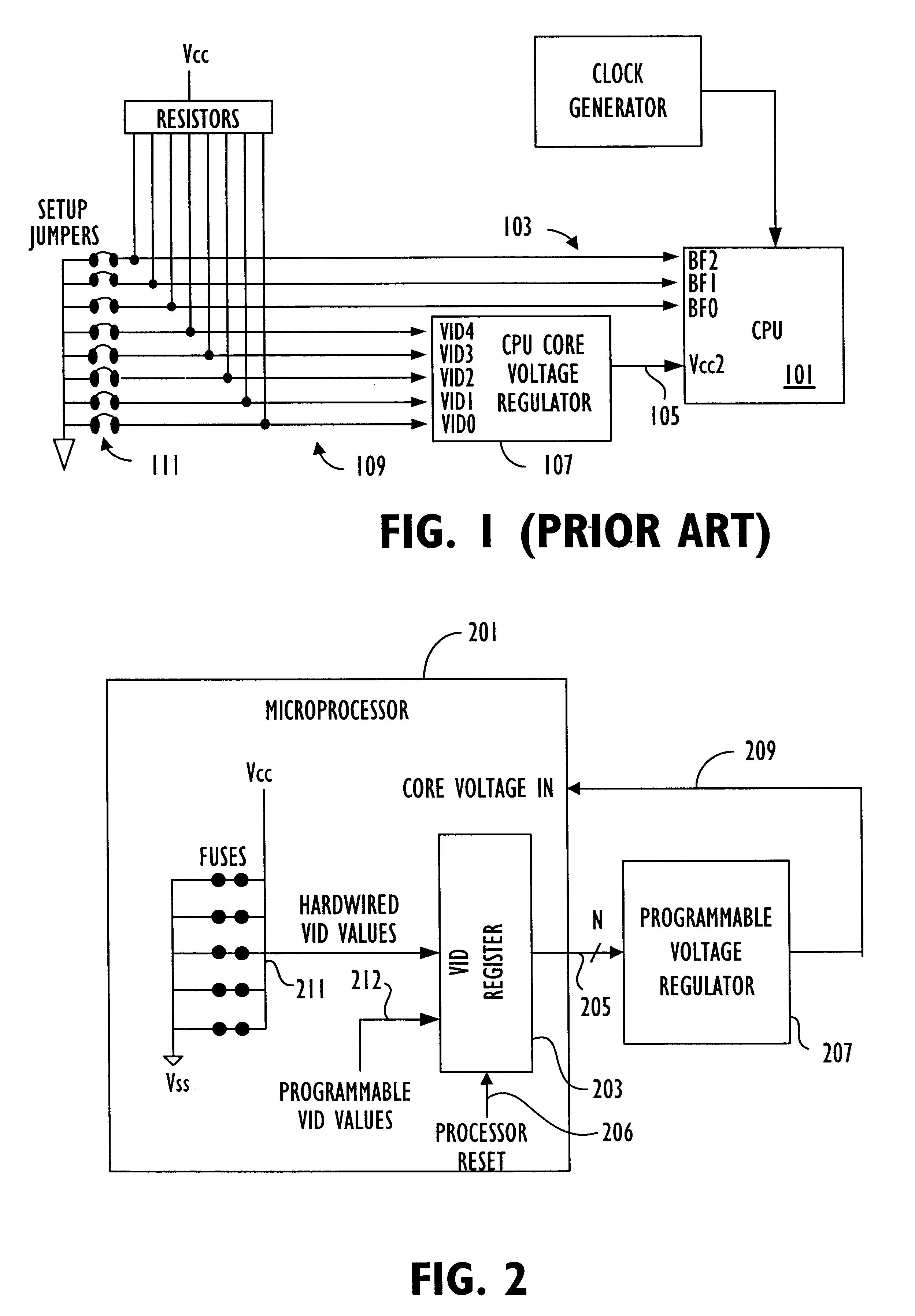
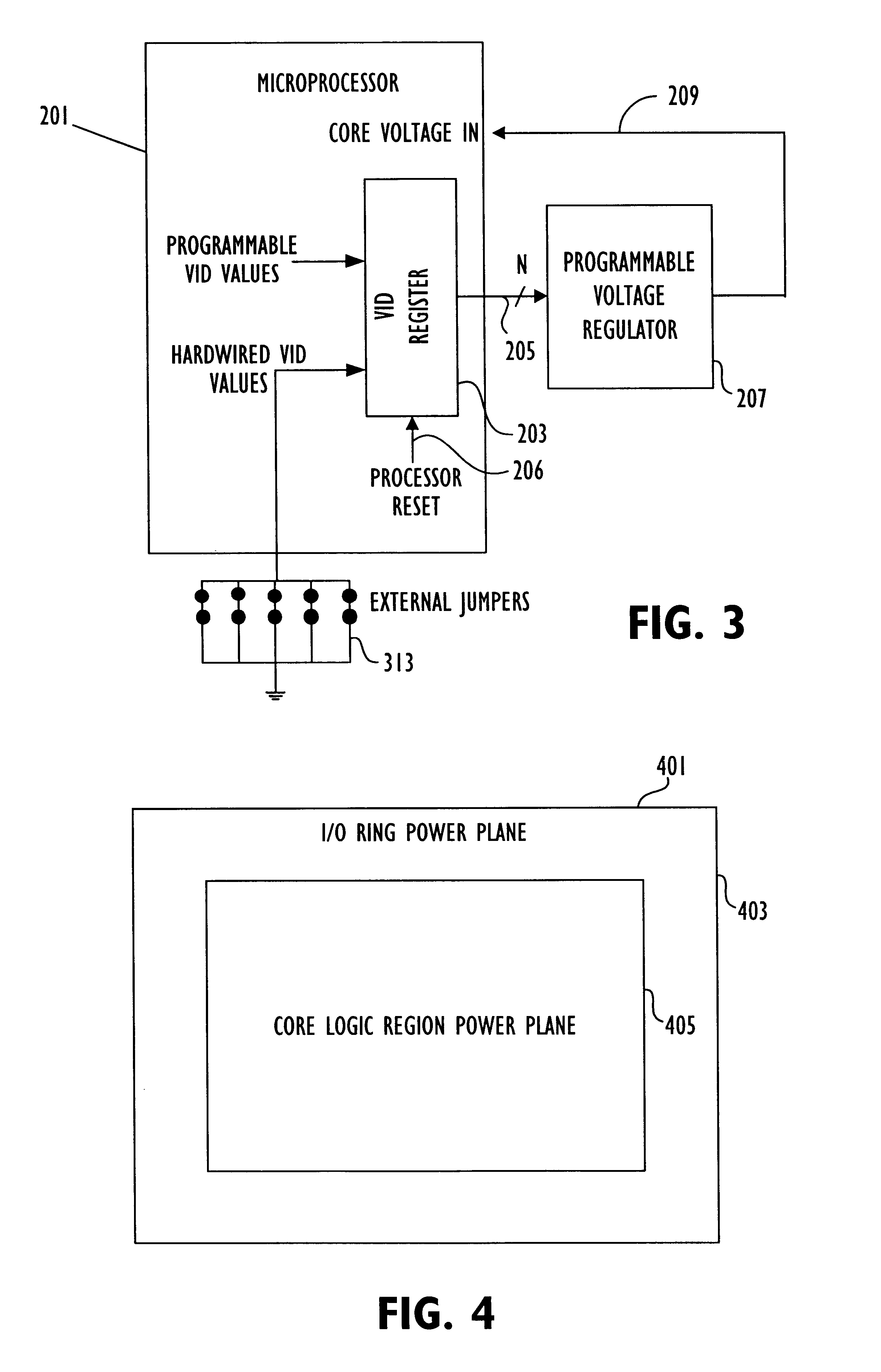
Referring to FIG. 2, an exemplary embodiment is illustrated. Microprocessor 201 includes programmable VID register 203 which supplies voltage identification (VID) values 205 to a programmable voltage regulator 207 to specify the core voltage 209 that is supplied to microprocessor 201. The programmable register receives a fixed VID value from fuse array 211.

Various configurations of fuses may be used for fuse array 211, which are described in detail in the patent application entitled, "INTEGRATED CIRCUIT PACKAGE INCORPORATING PROGRAMMABLE ELEMENTS", application Ser. No. 09 / 484,311, filed Jan. 18, 2000 and naming James John Casto, Qadeer Ahmad Qureshi and Hugh William Boothby as inventors, which application is incorporated herein by reference in its entirety. As described in the referenced patent application, fuse array 211 may be formed on the package of microprocessor 201 and may be formed of fuses and / or anti-fuses.

In addition to receiving the hardwired VID values from the fuse ar...


PUM


Abstract

A core voltage for a core logic region of an integrated circuit is specified by a programmable register on the integrated circuit. Output terminals on the integrated circuit are coupled to the programmable storage location and supply voltage control signals for a voltage regulator to specify the core voltage according to the contents of the programmable register. The output terminals may output a programmable voltage setting or a fixed voltage setting that specifies a default core voltage value, depending on reset conditions.

Description

1. Field of the InventionThe invention relates to integrated circuits and more particularly to controlling the voltage supplied to an integrated circuit.2. Description of the Related ArtIntegrated circuits such as microprocessors can be run at different clocks speeds and with different supply voltages. The determination of an appropriate clock speed and appropriate voltage for a particular microprocessor depends on many factors. For example, while higher clock speeds are generally desirable, a higher clock speed requires a higher supply voltage, which results in additional power consumption and additional heat, which needs to be dissipated. Microprocessors utilized in mobile applications are particularly sensitive to power dissipation and generally require the lowest power dissipation and thus require the lowest supply voltage that can achieve the rated clock speed. However, microprocessors used in desktop applications are less sensitive to power dissipation considerations.In genera...

Claims


Application Information

Patent Timeline
Patent Type & Authority Patents(United States)
IPC IPC(8): G06F1/26G06F1/32H01L23/544
CPCG06F1/26G06F1/3203G06F1/324G06F1/3296H01L23/544H01L2223/5444H01L2223/54473Y02B60/1217Y02B60/1285H01L2924/0002H01L2924/00Y02D10/00
Inventor QURESHI, QADEER AHMADMITCHELL, CHARLES WELDONCASTO, JAMES JOHN
Owner ADVANCED SILICON TECH
Why Eureka
Try Eureka