Supercharge Your Innovation With Domain-Expert AI Agents!

Very high-speed limiting electrical switchgear apparatus

a switchgear and high-speed technology, applied in the direction of switch power arrangement, snap-action arrangement, contact mechanism, etc., can solve the problems of high cost, extremely snappy opening and closing of the thomson effect actuator, and the mechanism of the apparatus suffers a great deal

Inactive Publication Date: 2004-08-17
SCHNEIDER ELECTRIC IND SAS
View PDF11 Cites 15 Cited by
  • Summary
  • Abstract
  • Description
  • Claims
  • Application Information

AI Technical Summary

Benefits of technology

The invention is a very high-speed electrical switchgear apparatus with the function of a limiting circuit breaker. It has a very fast opening and closing speed, but it is limited in its use due to its design and the cost of its components. The invention proposes a new design that overcomes the limitations of the prior art. It uses a drive mechanism and an energy storage spring to open and close the circuit breaker, and it has a high-speed actuator for opening and closing the contacts. The invention is compact, reliable, and cost-effective. It also allows for separation of the contacts and a limiting effect without the current intensity having exceeded a limiting threshold.

Problems solved by technology

Furthermore, the Thomson effect actuator requires its own electric power supply and, in case of failure of the latter, there is no subsidiary means of operating the apparatus.
Moreover, the apparatus thus designed is very specific with respect to low-voltage power circuit breakers of conventional design which constitute the vast majority of the range, so that its cost remains high.
Finally, the openings and closings by means of the Thomson effect actuator are extremely snappy, regardless of the type of fault.
The mechanism of the apparatus therefore suffers considerably during the opening and closing cycles.
However, the limiting function is only achieved by tripping of the circuit breaker, so that it does not enhance down-line selectivity in a distribution panel.
The circuit breaker obtained has very high performances, but separation of the contact fingers by electromagnetic reaction cannot take place before the current intensity has exceeded a limiting threshold.
Such a device does however present the shortcoming of being less reliable in the event of violent bouncing of the second contact in the separated position.

Method used


Image

  • Very high-speed limiting electrical switchgear apparatus
  • Very high-speed limiting electrical switchgear apparatus
  • Very high-speed limiting electrical switchgear apparatus

Examples


Embodiment Construction

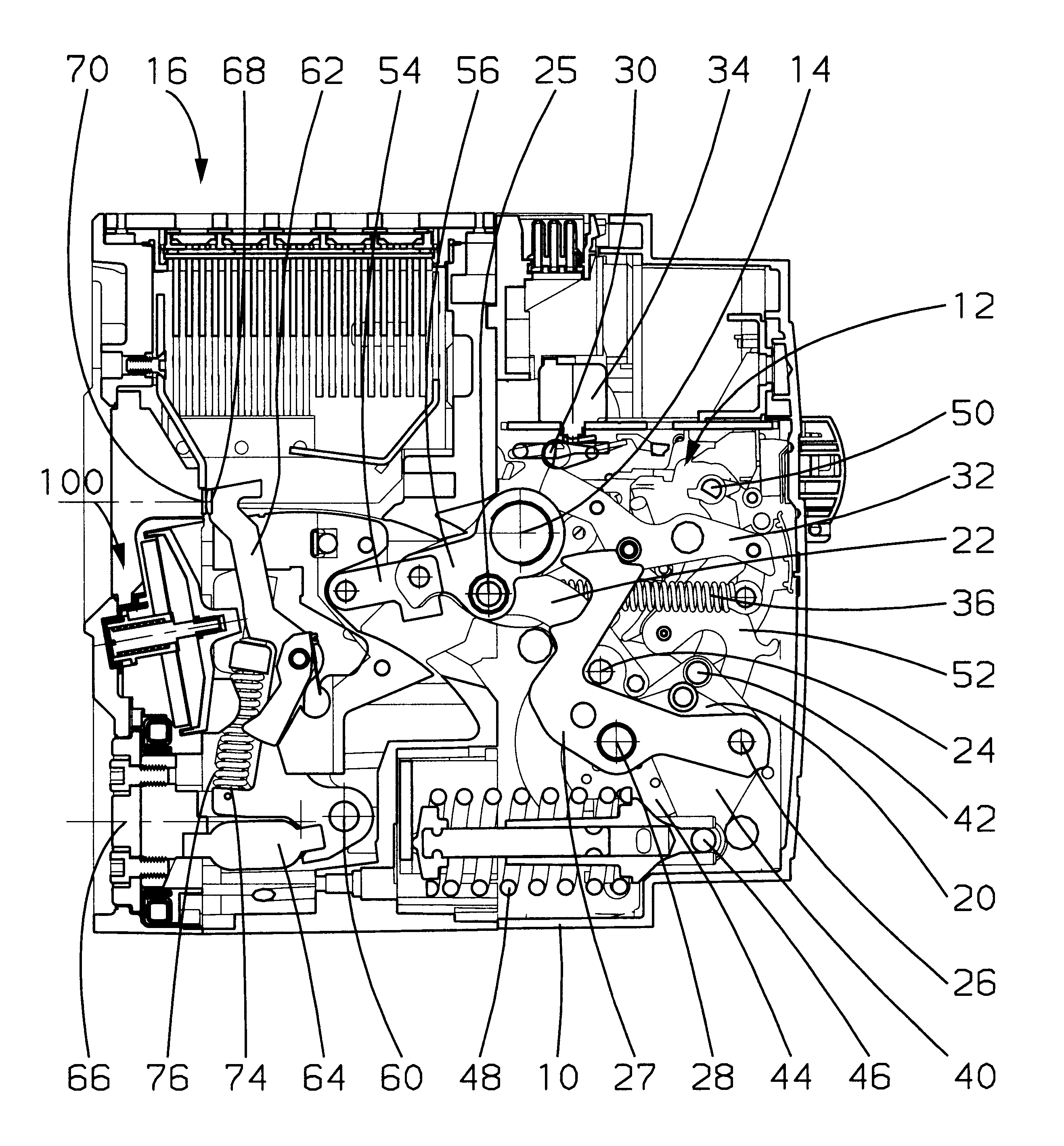
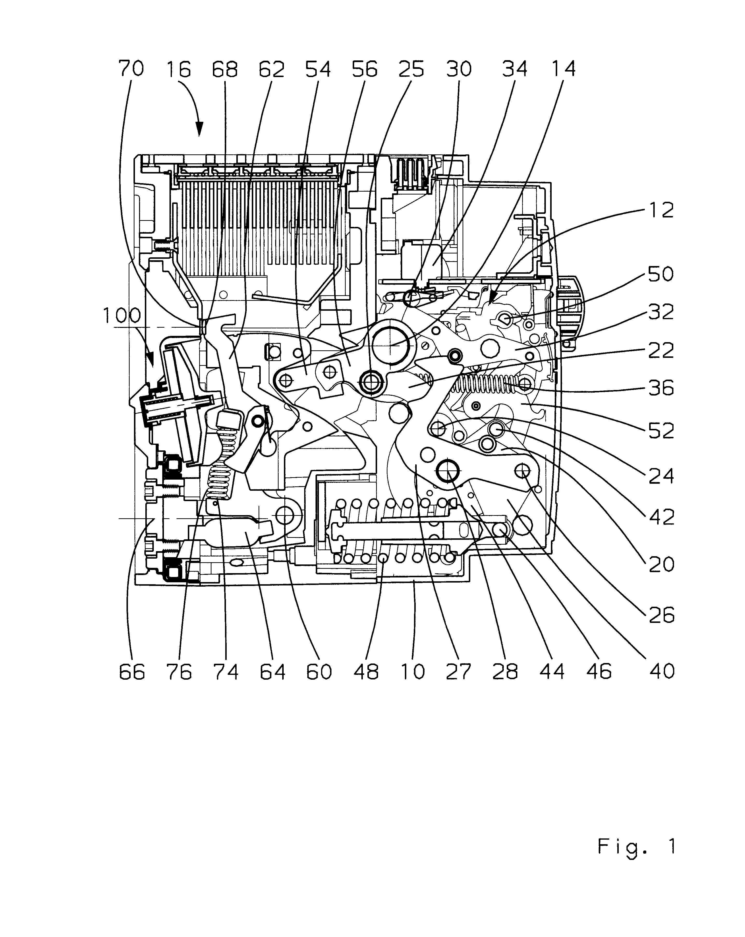
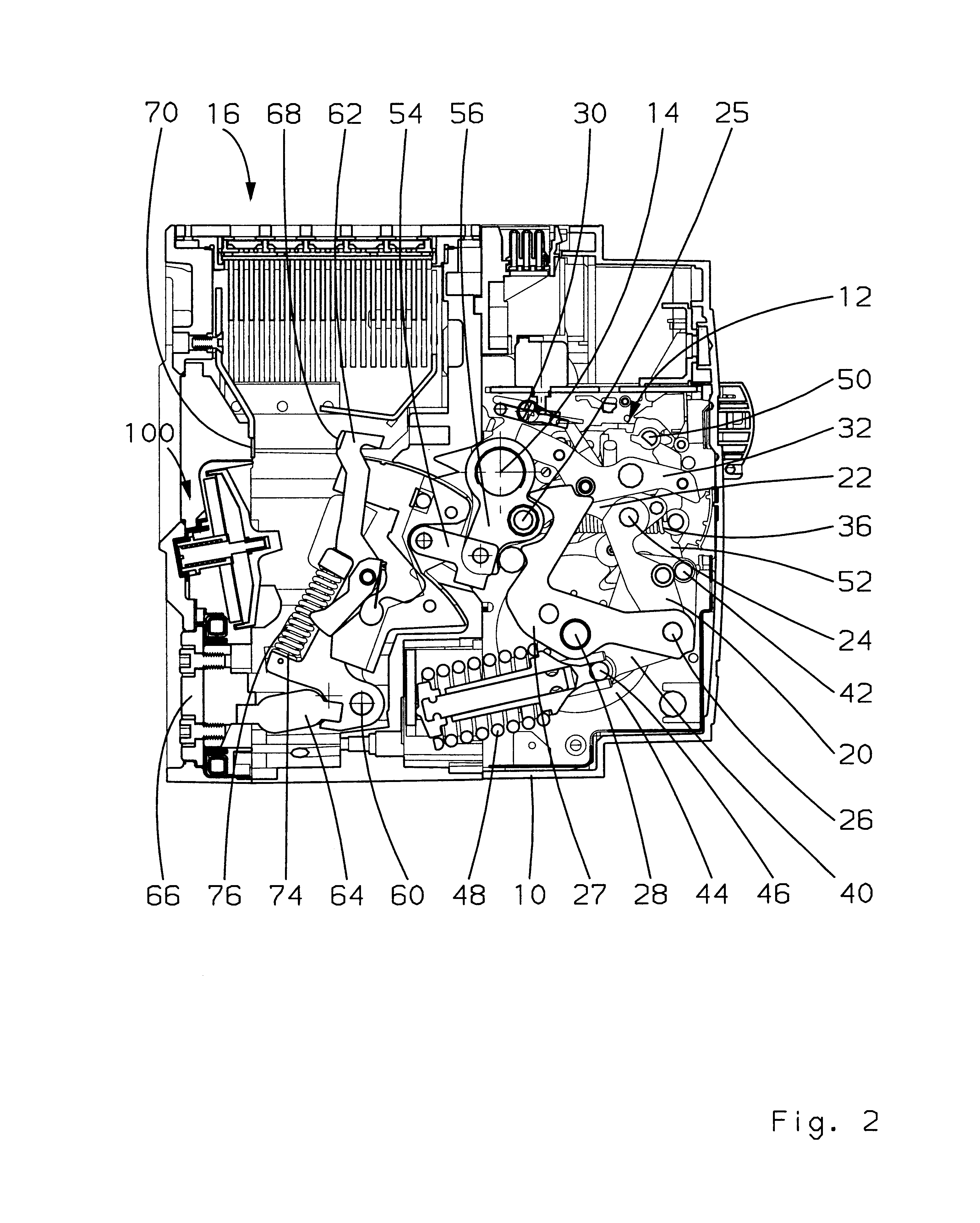
With reference to FIGS. 1 to 3, a case 10 of a low-voltage power limiting circuit breaker made of insulating material houses a drive mechanism 12 in its front part for driving a swivelling switching bar 14 which transmits the movements of the mechanism 12 to pole-units 16 of the apparatus situated in the rear part.

The drive mechanism 12 is supported by a frame, not represented, fixed with respect to the case 10, and comprises a toggle device having a pair of transmission rods 20, 22, articulated with respect to one another by means of a spindle 24. The upper rod 22 is mechanically coupled to the switching bar 14 by means of a spindle 25. The lower rod 20 is articulated by means of a spindle 26 on a latch 27 rotating around a fixed swivel-pin 28. An opening catch 30 locks the latch 27 in a loaded position by means of a gearing down lever 32. The opening catch 30 is actuated by means of an electromagnetic relay 34. An opening spring 36 is fitted between the spindle 25 and a pin fixed ...


PUM


Abstract

A limiting circuit breaker comprises two separable contacts 68, 70 and a mechanism 12 with energy storage 36 operated by an opening catch 30. The mechanism 12 drives a movable cage 58 between a closed position and an open position to perform opening of the contacts. One of the contacts is movable with respect to the cage 58 in the closed position and can thus take a separated position. A Thomson effect electromechanical actuator 100 is provided to drive the movable contact 68 to the separated position. A latch 80 enables the movable contact to be held in the separated position. In the event of a fault requiring a very high-speed response, separation of the contacts is obtained by means of the Thomson effect actuator and is then confirmed by opening of the mechanism. In other cases, only the mechanism operates to perform opening.

Description

The invention relates to a very high-speed electrical switchgear apparatus having the function of a limiting circuit breaker.STATE OF THE PRIOR ARTIn the document EP 0,309,311 a limiting circuit breaker is described with high-speed opening control of the contacts by Thomson effect, each pole-unit of which circuit breaker is equipped with a movable assembly having a movable main bridge forming a main circuit with a pair of stationary main contacts connected to current input terminal strips, and a movable arcing contact bridge forming, with a pair of stationary arcing contacts, an arcing circuit connected in parallel with the main circuit. A Thomson effect thrust means drives the movable assembly for opening of the main circuit and of the arcing circuit. A latching device holds the movable assembly in the open position against the bias of return springs tending to return the movable assembly to the closed position. A second Thomson effect thruster serves the purpose of unlatching the ...

Claims


Application Information

Patent Timeline
Patent Type & Authority Patents(United States)
IPC IPC(8): H01H3/00H01H3/22H01H71/24H01H71/12H01H3/30
CPCH01H3/222H01H3/3015H01H71/123H01H71/2418
Inventor BAGINSKI, PIERREBRUN, GREGOIREFERRAND, JEAN-PAULJOUBERT, JACQUESPELLEGRIN, CHRISTIANVACHER, RICHARD
Owner SCHNEIDER ELECTRIC IND SAS
Features
  • R&D
  • Intellectual Property
  • Life Sciences
  • Materials
  • Tech Scout
  • Unparalleled Data Quality
  • Higher Quality Content
  • 60% Fewer Hallucinations
Learn More