Car body and a method for producing a beam

a technology for a car body and a beam is applied in the field of car bodies to achieve the effects of reducing the cost of production, and improving the quality of production

Inactive Publication Date: 2004-08-24
BOMBARDIER TRANSPORTATION GMBH
View PDF18 Cites 0 Cited by
  • Summary
  • Abstract
  • Description
  • Claims
  • Application Information

AI Technical Summary

Benefits of technology

These objects are achieved by a car body of the initially defined kind which is characterized in that at least one of said beams includes an attaching member extending substantially in the longitudinal direction of the beam for engagement with at least a part of one or more components intended to be supported by the beam. As a part of said components, also intermediate attaching elements are included, for instance attaching rulers for standardized profile rail systems, such as C-rail systems. A further benefit achieved thanks to the invention is that such attaching elements easily can be positioned practically anywhere along the attaching member and also easily removed if required without leaving any considerable traces.
According to a further preferred embodiment, the attaching member is an integrated part of the beam. Joints for fixing the attaching member to the beam are therefore not needed, and an aesthetically attractive beam, free from splicing, is utilized.
According to a further preferred embodiment, the beam includes a sheet with a substantially constant thickness, and the recess is defined by the shape of the sheet. In this way, the attaching member in the form of the recess / bulge can be accomplished by, for instance, rolling of the sheet, and accordingly at a relatively low cost. The manufacturing of the beam does not need to be done by mechanical tooling (milling or the like) for the accomplishment of the recess / bulge, and accordingly unnecessary losses of material are avoided.
A further object of the invention is to provide a method for manufacturing of a beam for a car body of a vehicle, which method to a great extent should be suited for automatic, industrial manufacturing and results in a beam with such a design that the need for welded, riveted, and screwed joints, etc. for fixing further components to the beam can be considerably reduced. This object is achieved according to the invention by a method of the initially defined kind, characterized in that an attaching member, running substantially in the longitudinal direction of the beam, is arranged in the beam. The beam is elongated when it is ready for use, and the attaching member can easily be accomplished in connection with the extrusion or rolling of the beam to its final shape. The beam with the attaching member in the form of the recess / bulge can define a standardized profile rail and work as an engaging member relative to further components, such as interiors, cabling, bogie wagon equipment, etc. in the car body. Attaching elements for standardized profile rail systems can in the first place be used for engagement with the attaching member. These attaching elements then form a part of said components and can easily be moved from a position to another and be completely removed for moving or removal of said components.
According to a preferred embodiment, the beam includes a sheet and the attaching member is accomplished by rolling of the sheet. Expensive mechanical tooling, such as milling, for accomplishment of the attaching member is thereby avoided. Practically no losses of material occur.

Problems solved by technology

The arrangement of such joints is a labor intensive and costly factor for the manufacture of such car bodies.
Furthermore, welded joints cause irregularities in the even surfaces of, for instance, the wall elements and components attached to a beam.
Moreover, irregularities caused by welded joints result in inexact tolerances of the walls, for instance, so that problems can occur with the fitting between different parts such as walls and floors.

Method used


Image

  • Car body and a method for producing a beam
  • Car body and a method for producing a beam
  • Car body and a method for producing a beam

Examples


Embodiment Construction

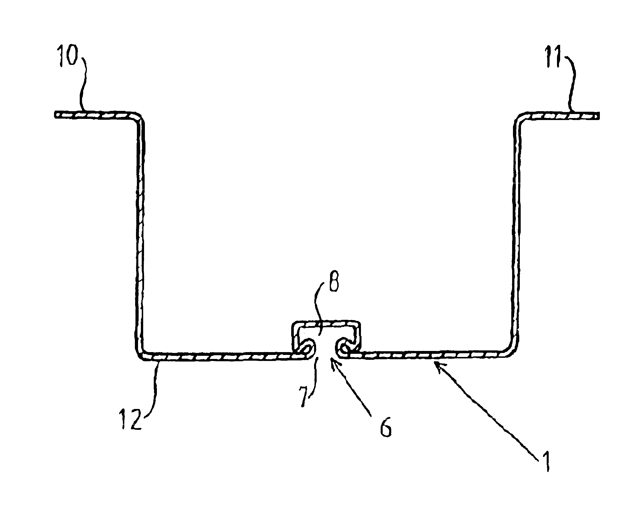
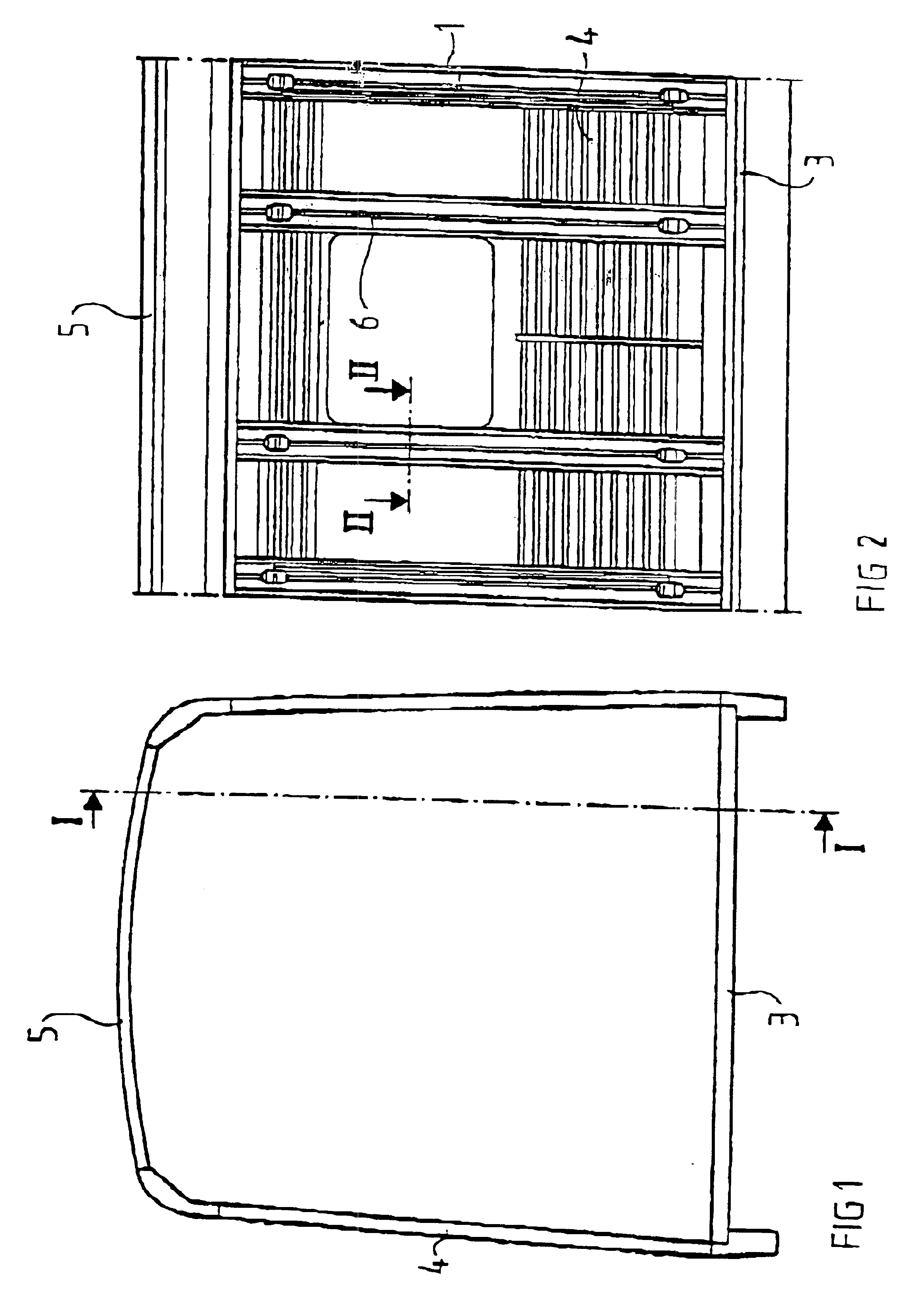
FIG. 1 discloses a cross-section of a car body for a vehicle, in this case a rail vehicle, namely a train wagon. The car body includes a number of beams 1, which form a support for wall elements in the form of sheets 3, 4 and 5, which surround and define an inner space of the car body. Said sheets form the floor 3, the side walls 4, and the roof 5 of the vehicle.

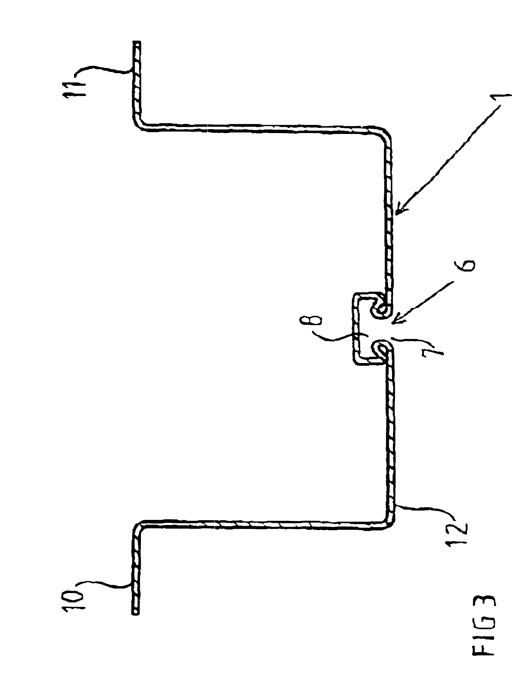
Each beam 1 includes a sheet with a substantially constant thickness. The sheet is formed so that it defines a recess 6 turned away from or, as in this cases, towards the inner space of the car body. The recess 6 is arranged to engage at least one part of one or more components (not shown), and thereby support them. Such components may, for instance, include interiors, such as tables, chairs, shelves, or channels, or the like, for receiving cabling etc.

The recess 6 extends with a substantially constant cross-section in the longitudinal direction of the beam 1 and along a considerable part, preferably the whole, of its length...


PUM


Abstract

A car body for a rail vehicle including a plurality of beams (1) arranged to carry one or more wall elements (3-5). At least one of said beams (1) includes an attaching member (6), extending substantially in the longitudinal direction of the beam, for engagement with at least a part of one or more components intended to be supported by the beam (1).

Description

THE BACKGROUND OF THE INVENTION AND PRIOR ARTThe present invention refers to a car body for a rail vehicle. In particular, it refers to a car body including a number of beams arranged to carry one or more wall elements. Furthermore, the invention refers to a method for manufacturing of a beam to the car body of a vehicle.The term "wall elements" should be considered in a wide sense and may include a floor, a roof, and side walls of the vehicle. In particular, they include sheets which are supported by beams.The term car body should be seen in a wide meaning and includes all types of shell constructions arranged to surround and define the interior of a vehicle.The term "beam" concerns all the reinforcing and supporting beams or braces which are arranged to carry the floor, the walls, and the roof of the car body and which, in addition, can be utilized as a support for further components in the car body.The invention is particularly advantageous for car bodies for train wagons, and wi...

Claims


Application Information

Patent Timeline
Patent Type & Authority Patents(United States)
IPC IPC(8): B61D17/04
CPCB61D17/04Y02T30/34Y02T30/00
Inventor SJOBACK, CONNY
Owner BOMBARDIER TRANSPORTATION GMBH
Why Eureka
Try Eureka