Complete fluid exchange system for automatic transmissions

a technology of automatic transmission and fluid exchange system, which is applied in the direction of liquid handling, machines/engines, packaging goods types, etc., can solve the problems that the importance of illustrating alternative methods to express the same principles of the novel art of my device is not important enough, and achieves the effects of high efficiency, rapid and cost-effective, and easy operation

Inactive Publication Date: 2004-08-24
VIKEN JAMES P
View PDF74 Cites 25 Cited by
  • Summary
  • Abstract
  • Description
  • Claims
  • Application Information

AI Technical Summary

Benefits of technology

Thus the reader will see that the Complete Fluid Change System provides a unique, highly effective, convenient, compact, easy to operate, rapid and cost efficient device to institute a Complete Fluid Exchange in vehicular automatic transmissions.
The device allows the operator to provide Complete Fluid Exchanges to vehicular automatic transmissions faster and easier, using less fresh fluid in the process. It provides before and after fluid samples for vehicle owners. For these reasons mentioned, it is novel art that is commercially useful and valuable in the automotive and vehicular maintenance industry.

Problems solved by technology

These many possible small changes and alternative methods to express the same principles of the novel art of my device are not important enough to illustrate in the drawings.

Method used


Image

  • Complete fluid exchange system for automatic transmissions
  • Complete fluid exchange system for automatic transmissions
  • Complete fluid exchange system for automatic transmissions

Examples


Embodiment Construction

--FIG. 3--the Second Embodiment

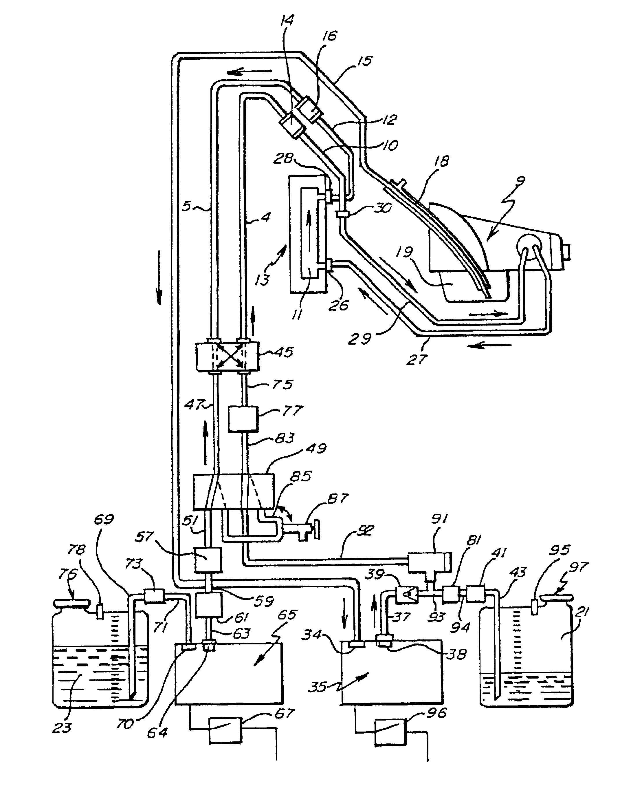
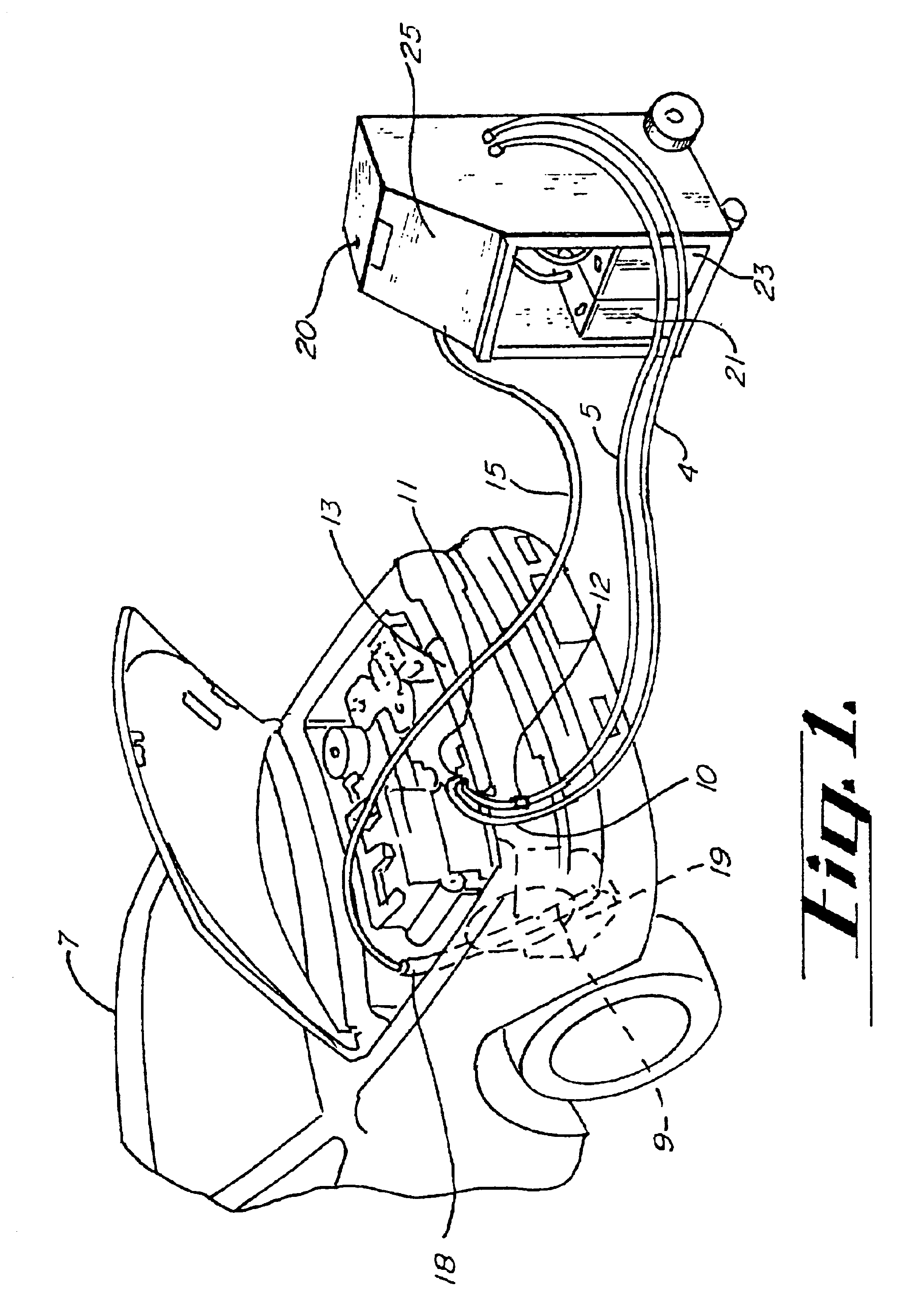
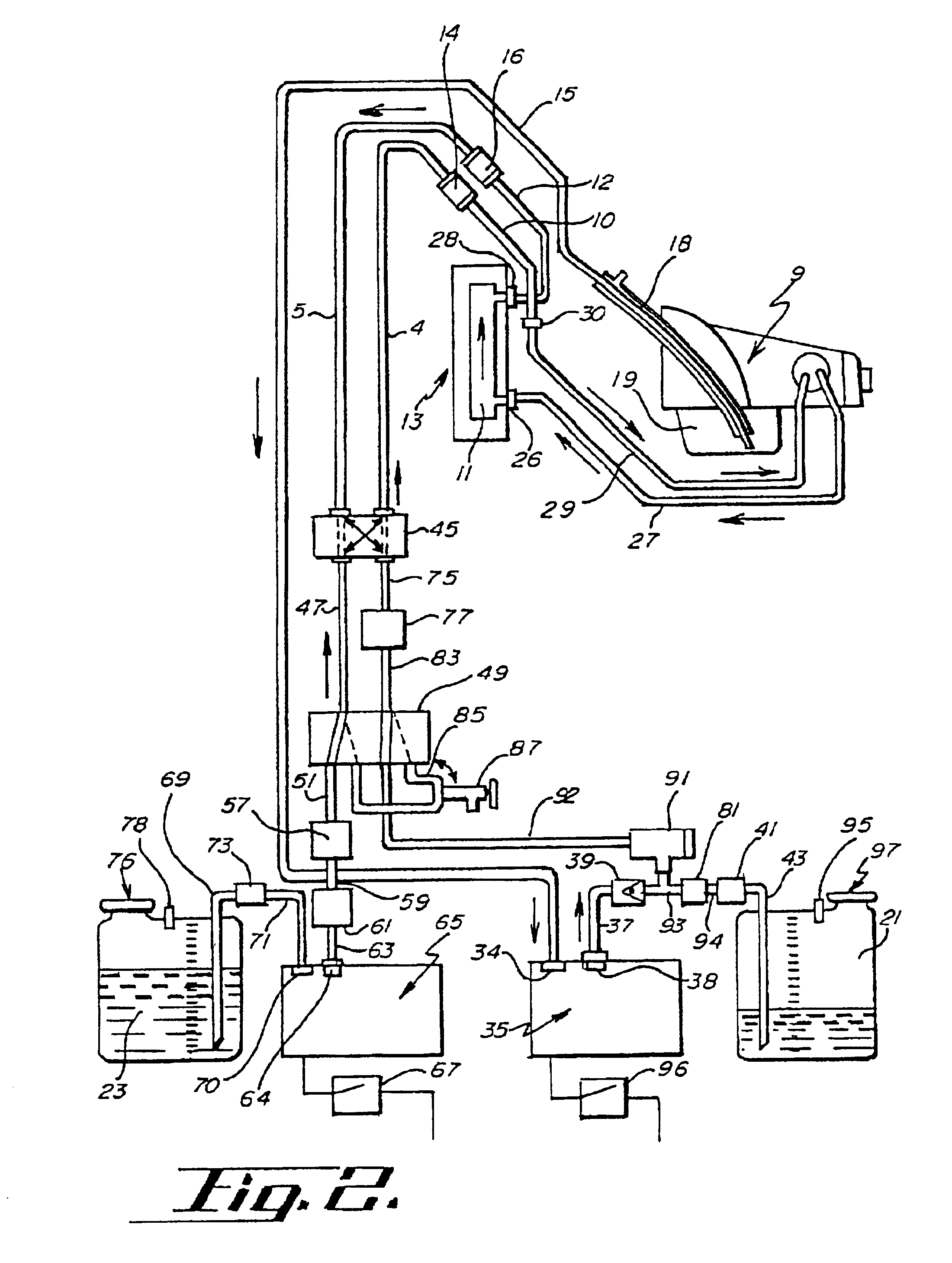
FIG. 3 is an illustration of the second and preferred embodiment of the Invention, the Complete Fluid Exchange System which like the embodiment illustrated in FIG. 2, has been randomly interconnected to both sides of the opened cooling circuit comprised of cooling outlet line 27, transmission 11 inside radiator 13 and cooling return line 29, each of which form together as connected, the complete cooling circuit 27 / 11 / 29 of transmission 9. Both embodiments share most of the integral components and / or means utilized. The second and preferred embodiment is electrically powered and electronically controlled by a microprocessor system provided with suitable software. The microprocessor receives electronic indicating signals from electronically indicating sensors and meters, processes them according to the software specifications and then elicits electronic command signals to individual components which are electronically controlled and electrically powered....


PUM

PropertyMeasurementUnit
pressureaaaaaaaaaa
fluid flow rateaaaaaaaaaa
flow rateaaaaaaaaaa

Abstract

An improved system for changing the fluid of vehicular automatic transmissions and the like, which has the capability to provide a complete fluid exchange faster and with less usage of fresh fluid in a manner that is easier to operate. This is accomplished by the system's unique capability to extract used fluid and replace it with fresh fluid at a faster, balanced rate than before possible in prior art. This is accomplished by decreasing or removing restriction from the exhausting of the used fluid and introducing fresh fluid at more than one locus. The unique, novel capability of the invention to use a dual use pan access tube to combine a static change with a dynamic change, and to introduce fresh fluid into the transmission from two different loci instead of one as in all prior art, allows the fluid exchange to be completed in a shorter time with less use of fluid. These improvements increase the commercial utility and value of complete fluid changing in automatic transmissions and should extend its commercial viability as a routine maintenance procedure in the vehicular or automotive industry.

Description

This invention relates generally to changing the fluid of vehicular automatic transmissions and more specifically to a complete static and dynamic combination of fluid flushing, purging, cleaning and replacement of used transmission fluid with fresh fluid to the torque convertor, other typically inaccessible transmission components, and the transmission as a whole.OBJECTS AND ADVANTAGESThe new invention comprehensively coordinates the utilization of both static and dynamic fluid changing in a unique manner as a combined means to effectively institute a Complete Fluid Exchange in the least amount of time practical without harming the transmission or vehicle and with the least use of fresh fluid feasible. These objects have significant commercial value.Prior art in the area of dynamic fluid changing in automatic transmissions has been problematic in several serious ways that have limited the commercial viability of its use in every day automotive and vehicular preventative maintenance...

Claims


Application Information

Patent Timeline
Patent Type & Authority Patents(United States)
IPC IPC(8): F01M11/04F16H57/04F01M11/02
CPCF01M11/04F01M11/0458F16H57/0408
Inventor VIKEN, JAMES P.
Owner VIKEN JAMES P
Why Eureka
Try Eureka