Heart rate monitor and heart rate measuring method

a heart rate monitor and heart rate technology, applied in the field of heart rate monitors, can solve the problems of measurement errors, decreased blood flow, and difficulty in some cases, and achieve the effects of improving patient comfort, improving patient comfort, and improving patient comfor

Inactive Publication Date: 2004-08-31
NIPPON SEIMITSU SOKKI KK
View PDF11 Cites 169 Cited by
  • Summary
  • Abstract
  • Description
  • Claims
  • Application Information

AI Technical Summary

Problems solved by technology

However, the prior arts described above have the following problems to be solved.
Next, in the method of optically detecting a pulse rate from a blood vessel of a lobe, if a subject person does hard exercise such as running, there is the possibility of a measurement error occurring when the pulse rate is optically detected under the influence of body vibrations.
Even if the pulse rate is to be measured at a blood vessel where arteriovenous anastomosis exists as the blood vessel of a lobe, the aforementioned arteriovenous anastomosis has the function of adjusting bloodstream based on correlation between outside temperature and body heat, and therefore the bloodstream is decreased by this adjustment function to make the measurement difficult in some cases.
Further, in the method of detecting pressure pulsation by mechanical vibration from an artery near a body surface, body vibration has more influence than in the aforementioned method of optically detecting a pulse rate, and there is the possibility that a measurement error becomes large especially in the pulse rate detection during exercise.
However, the burden that a measured region is pressed by the cuff or the like is imposed on the subject person during measurement.
However, since heart rate measurement continues for a long time and measurement is needed during exercise, it is not preferable that the measured region is pressed by a cuff or the like.
However, since a thick artery of a human body is not normally located near a body surface, the accurate heart rate cannot be taken even if light is emitted from the body surface to try to detect the light after reflected or transmitted at or through the artery in a non-pressed state.

Method used


Image

  • Heart rate monitor and heart rate measuring method
  • Heart rate monitor and heart rate measuring method
  • Heart rate monitor and heart rate measuring method

Examples


example 2

(Fitting Example 2)

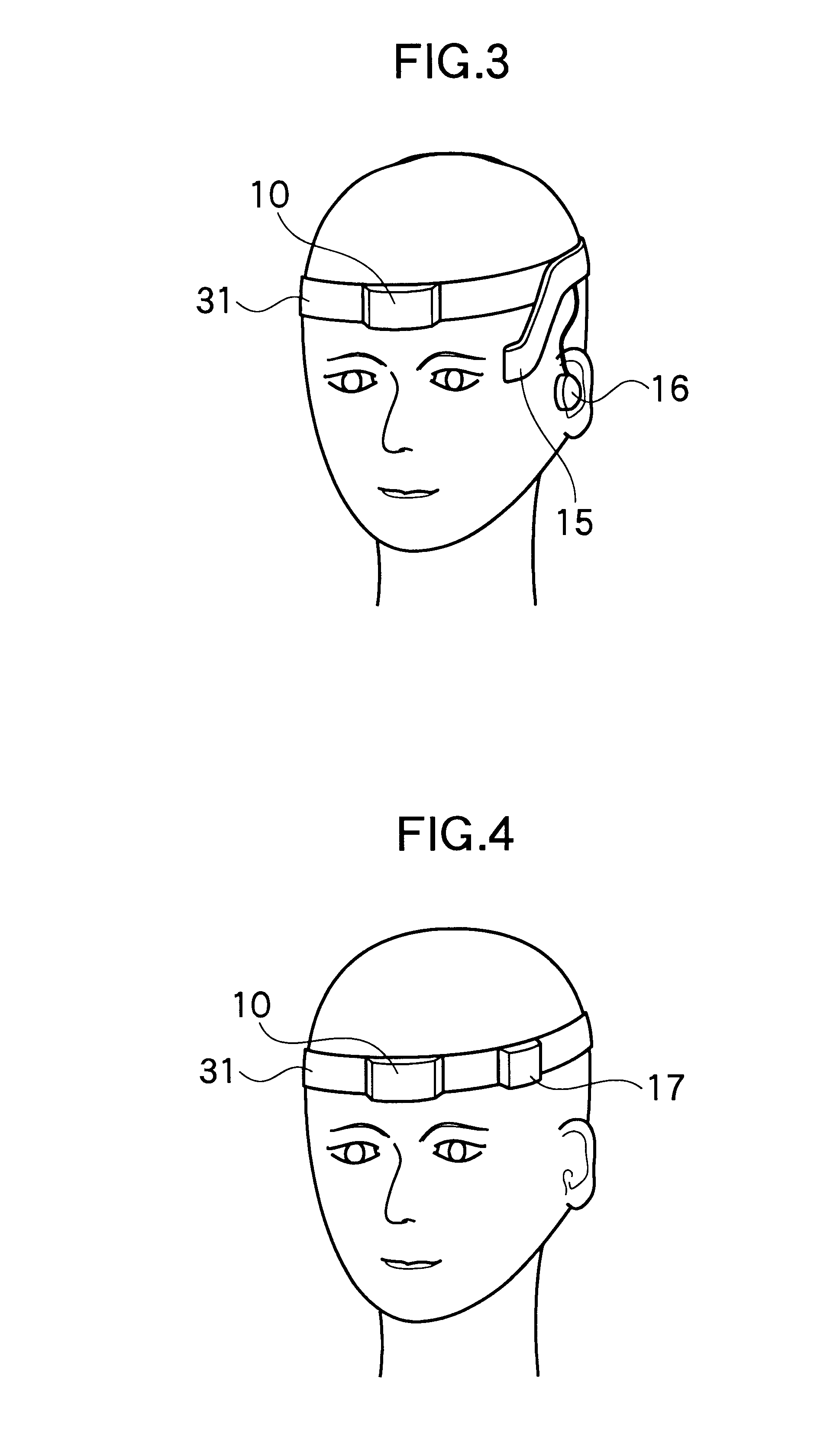
FIG. 4 shows an example in which the heart rate monitor 10 and the bone conduction element 17 are placed at the head band 31 as shown in FIG. 3.

The bone conduction element 17 transmits a synthetic voice signal from the CPU 14 as a vibration, and therefore a subject person can hear the synthetic voice even if there is noise around him or her.

If this constitution is adopted, the heart rate monitor 10 and the bone conduction element 17 can be both placed on the head band 31, which can provide a simple design and is preferable in handling.

example 3

(Fitting Example 3)

FIG. 5 shows an example in which the heart rate monitor 10 and the transmitter 18 are placed on the head band 31 as shown in FIG. 3.

The transmitter 18 transmits a heart rate signal from the CPU to the receiver by radio.

The constitution in which the heart rate signal received at the receiver can be, for example, further stored, printed, displayed and analyzed can be provided. In order to feed back the date to the subject person, the constitution using an optical display or a synthetic voice is preferable.

If this constitution is adopted, the heart rate monitor 10 and the transmitter 18 can be both placed on the head band 31, which can provide a simple design, and is preferable in handling.

Here, the aforementioned (Fitting example 2) and (Fitting example 3) are the fitting examples suitable for heart rate measurement on the occasion of doing sports such as, for example, swimming, athletic sports, and a ball game, which give a shock to a head or require vigorous motio...

example 4

(Fitting Example 4)

FIG. 6 is an example in which the heart rate monitor 10 and the display unit are placed at an eyeglass frame 32.

In this example, the heart rate monitor 10 is placed at a temple part of the eyeglass frame 32, and therefore a superficial temporal artery, a zygomatico-orbital artery and the like can be used as an artery at which the heart rate is detected. As the display unit, the display 15 using liquid crystal or the like as in the example shown in FIG. 3 may be used, but the constitution in which a head mound display is used is also preferable.

It goes without saying that the earphone 16 and / or the bone conduction element 17 can be used.


PUM


Abstract

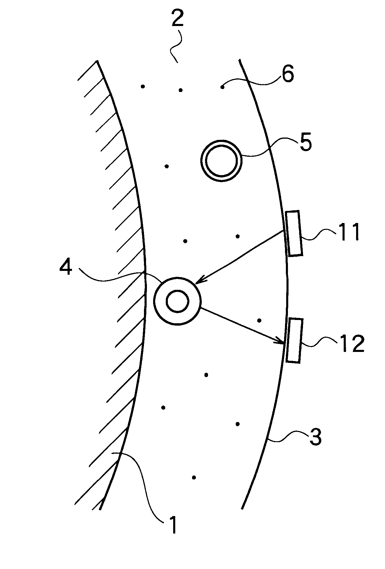
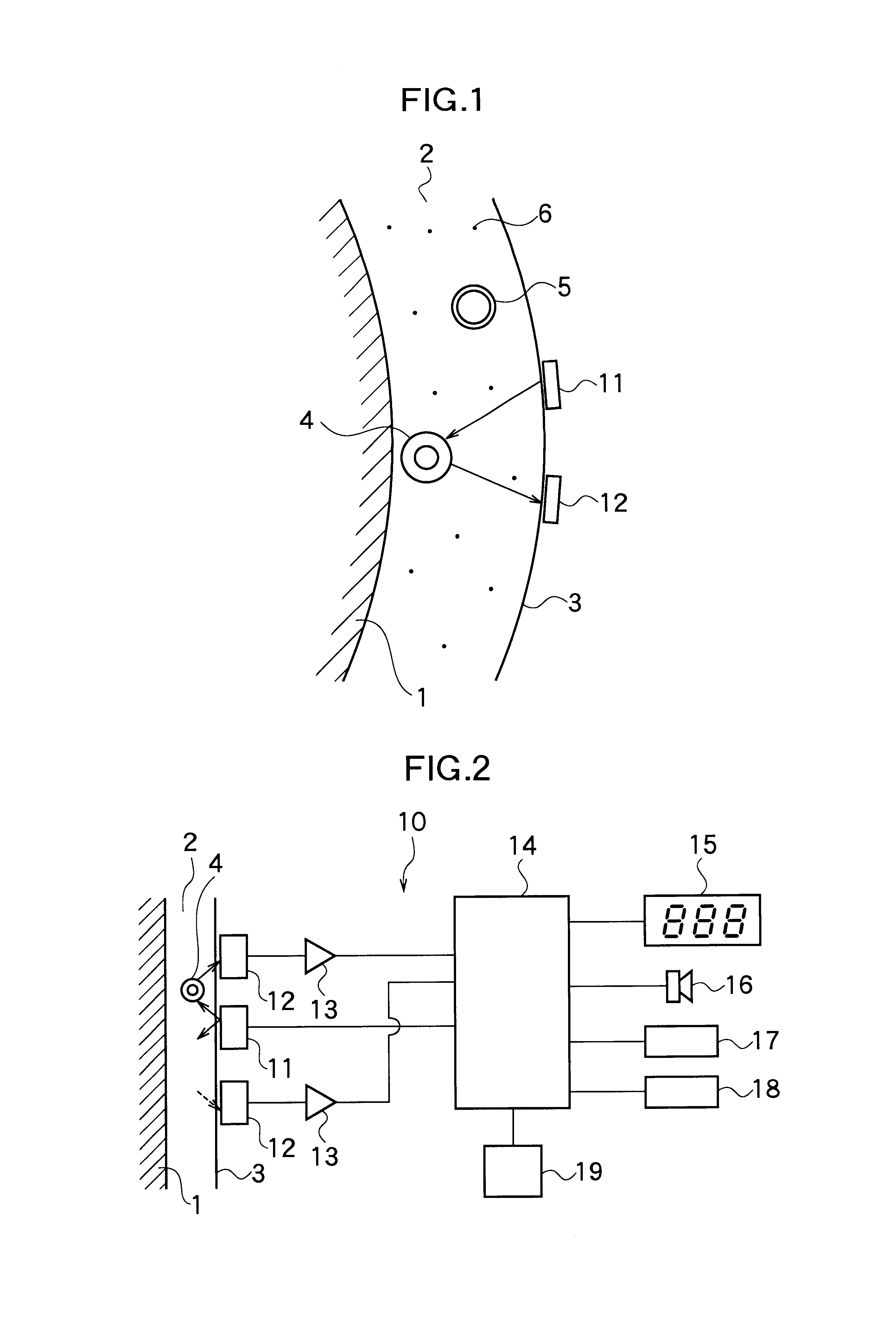
Accurate occurrences of pulsation per unit time, that is, a heart rate is measured with a burden on a subject person being reduced to be very small and without being susceptible to body vibrations accompanying exercise. A heart rate monitor is produced, in which a light-emitting element 11 and a light-receiving element 12 are fitted to a head of a human body, light from the light-emitting element 11 is reflected at or transmitted through a subcutaneous artery 4 and/or blood running in the subcutaneous artery, the reflected or transmitted light is detected at the light-receiving element 12, and by using a CPU 14, the pulsation of the subcutaneous artery 4 and/or a change in bloodstream running in the subcutaneous artery 4 is measured from a change in intensity of the light detected at the light-receiving element 12, a pulse rate of the change in the bloodstream per unit time is calculated from this measured value, and the calculated pulse rate of the change in the bloodstream per unit time is regarded as a heart rate.

Description

1. Field of the InventionThe present invention relates to a heart rate monitor for measuring the heart rate of a subject person while doing exercise such as running, jogging and walking, while doing light exercise, or during medical treatment.It should be noted that the heart rate in this invention means "occurrences of pulse per unit time".2. Description of the Related ArtAs a method of measuring a heart rate, there are conventionally a method of detecting an electrocardiographic signal from electrodes attached to an area near a heart as disclosed in Japanese Patent Application Laid-open No. 60-116325, a method of optically detecting a pulse rate from a blood vessel of a lobe as disclosed in Japanese Patent Application Publication No. 61-43057, a method of detecting pressure pulsation by mechanical vibration from an artery near a body surface as disclosed in U.S. Pat. No. 4,038,976, and a method in combination with a hemodynamometer as disclosed in Japanese Patent Application Laid-...

Claims


Application Information

Patent Timeline
Patent Type & Authority Patents(United States)
IPC IPC(8): A61B5/00A61B5/0245
CPCA61B5/0059A61B5/6814A61B5/6816
Inventor TAKAHASHI, YOSHIKAZUBAKER, WAYNESHIOGAI, HAJIMEKOSHINO, SHINJIMITSUHASHI, SHINTARO
Owner NIPPON SEIMITSU SOKKI KK
Why Eureka
Try Eureka