

Stereo images with comfortable perceived depth
a stereoscopic image and depth technology, applied in the field of stereo image production, can solve the problems of not matching the perception of users, the type of stereoscopic display system does not match the user's perception, and many viewers will find the resulting images uncomfortable to view, and no details are currently available about the operation method of this system
- Summary
- Abstract
- Description
- Claims
- Application Information
AI Technical Summary
Problems solved by technology
Method used
Image

Examples
first embodiment
A first embodiment will be described in which the camera separation, A, is calculated from other input data, for stereoscopic photographs taken with a physical camera or cameras.
We consider the situation where a photographer has composed the desired view, including the camera position and focal length (zoom), and wishes to know how far apart to take the left and right image to capture the correct disparity range for the target display. This naturally fits into a typical photography session where the photographer composes a shot by setting zoom and position before taking the shot.
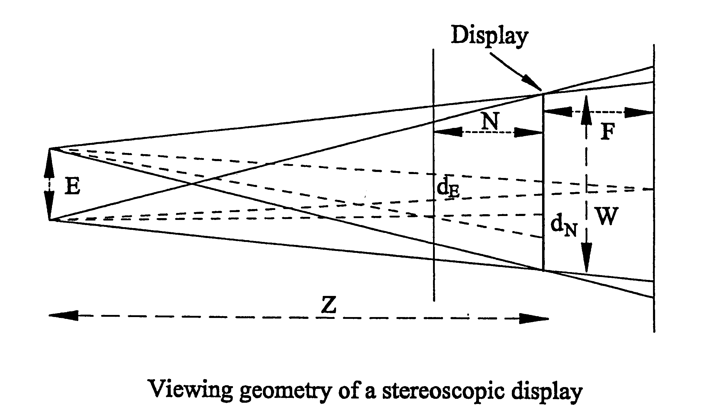
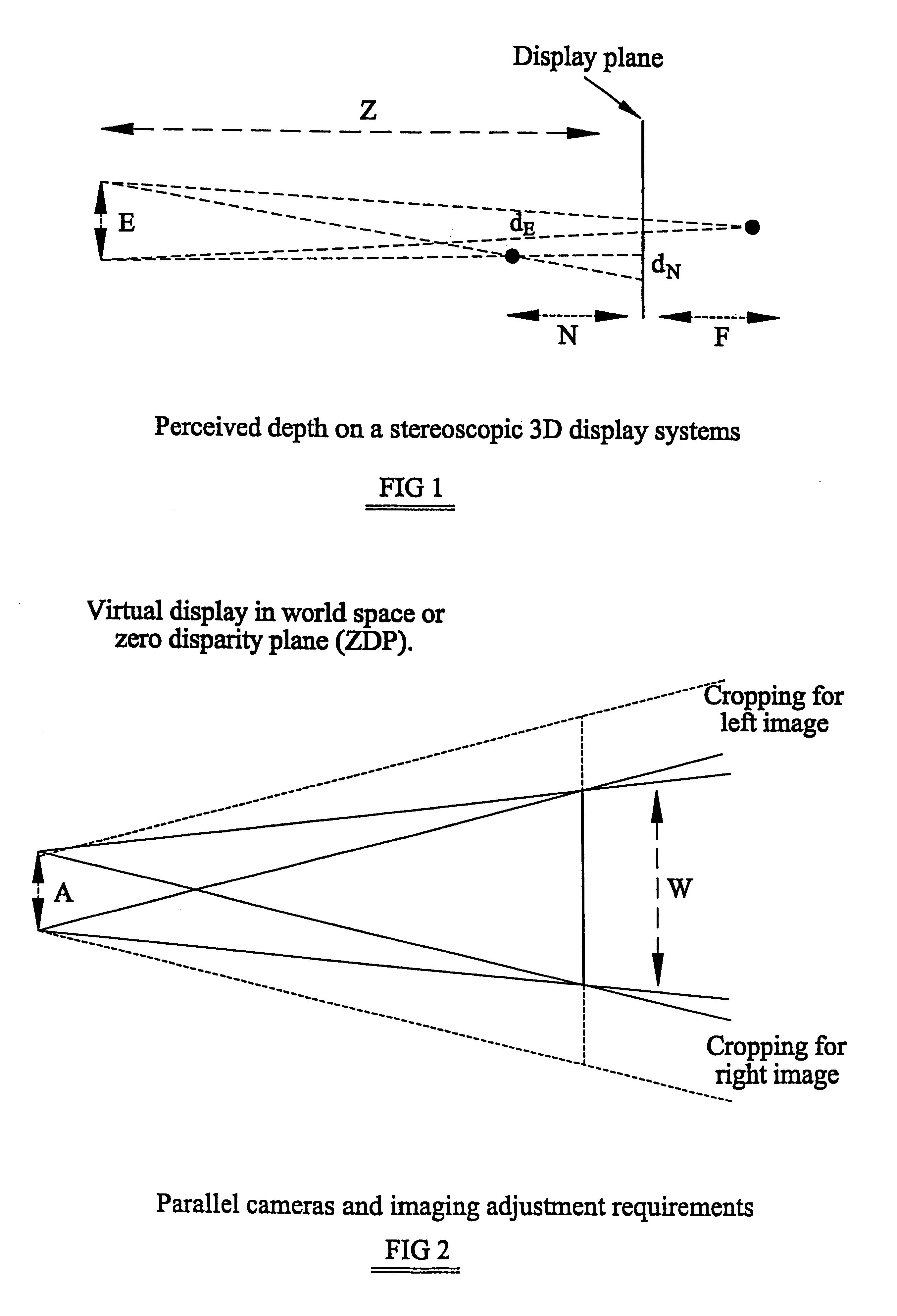
Initially, details of the display and viewer are required. These parameters (see FIG. 3) include:
Display Parameters
N maximum perceived depth of any object in front of the display plane
F maximum perceived depth of any object behind of the display plane
W Physical width of the viewing area of the display, or partial area in which the image will be displayed.
Z Viewing distance of the display.
Viewer Parameters
E E...
second embodiment
A second embodiment will now be described in which camera separation is calculated from other input data, for stereoscopic photographs taken with a real camera (when .theta., or f, may be altered).
In a situation where the field of view of the camera may be altered after setting up the view, with a purpose built sltereoscopic camera, with an accurately controlled camera, or with Computer Graphics cameras, a view closer to the original choice of the photographer may be obtained.
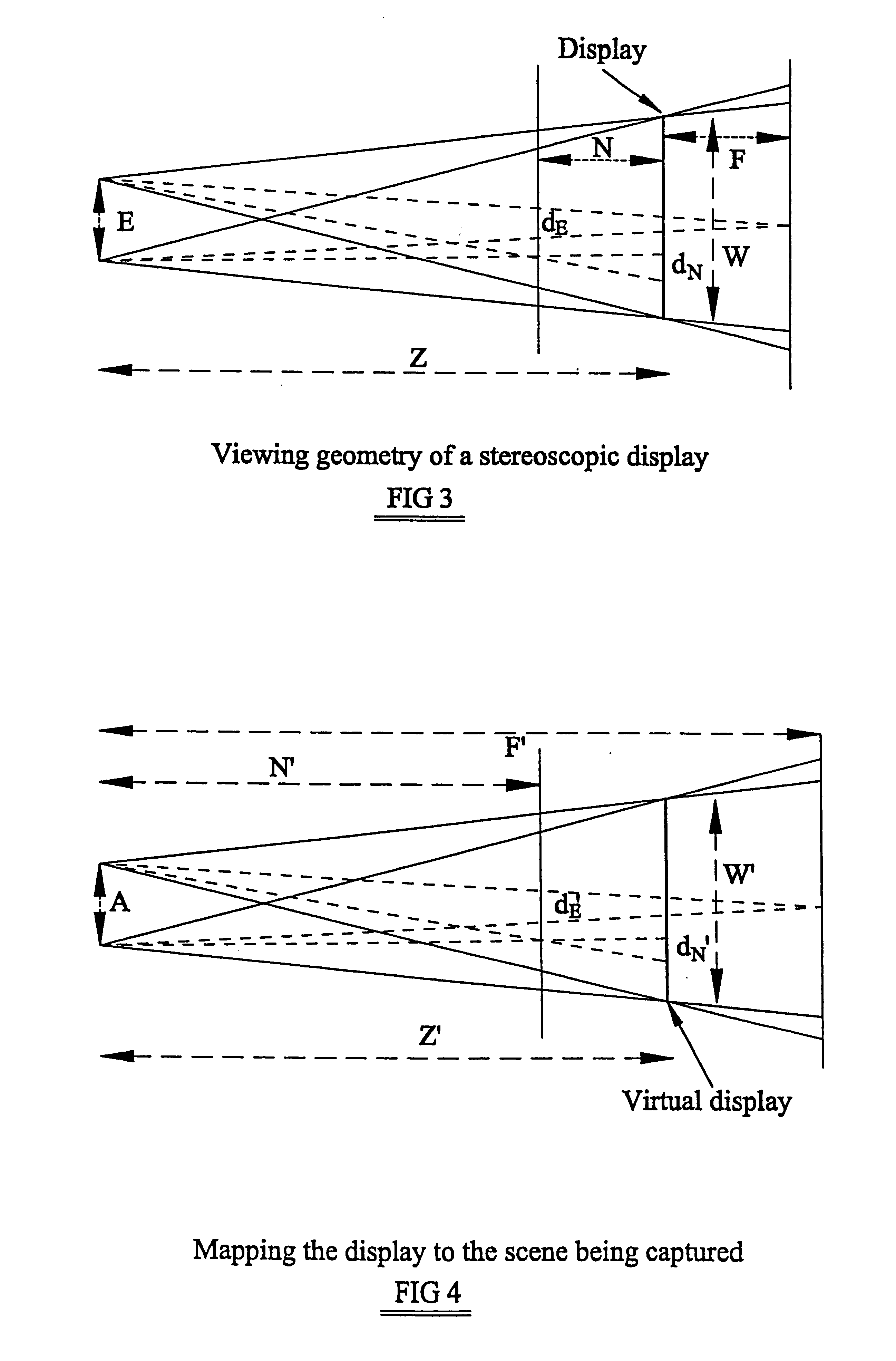
In this case equations [1] and [6] are followed as before. In this case the field of view will be expanded to encompass the extra image width which will later be cropped.
W'=2Z' tan(.theta. / 2)=Z'W.sub.f / f [16]
W (the real display width) is known, as is W'--this giving the scaling between the display and the worlds:
S=W' / W [17]
The maximum disparities, d.sub.N and d.sub.F are then scaled up to match the size of the virtual display, giving the values for d.sub.N ' and d.sub.F '. From these A, the camera separation, ...
third embodiment
A third embodiment will be described in which the field-of-view of focal length (zoom) is computed from other input.
In cases where the camera separation is fixed, the zoom can be adjusted to achieve the desired comfortable perceived depth on the display.
There are advantages to a design of stereoscopic camera in which zoom is.controlled by altering the camera separation, perhaps when there are two, or more, lenses on the camera to capture the stereoscopic images simultaneously. Other examples are where there is a fixed separation (e.g. for AGFA camera+Pentax image splitter) but the zoom can be adjusted over a range to help match differing scene depth ranges. This also occurs with certain video camera adapters where the zoom may be easier to control than the separation. It also can have a benefit where the zoom is controlled accurately but the separation is not controlled accurately. The separation is set and measured and the zoom adjusted to precisely match the scene depth range to t...
PUM
 Abstract
Description
Claims
Application Information