
Tiltable boat top

a boat top and tilting technology, applied in the field of tilting boat tops, can solve the problems of not offering the protection and sturdiness desired, certain conventional boat tops cannot remain upright while, and other standard tops do not provide side spray protection, so as to achieve convenient storage and reduce wind resistance

Inactive Publication Date: 2004-10-05
SMARTOP
View PDF17 Cites 35 Cited by
  • Summary
  • Abstract
  • Description
  • Claims
  • Application Information

AI Technical Summary

Benefits of technology

Thus, with the problems and disadvantages of prior boat tops, the present invention was conceived and one of its objectives is to provide a tiltable boat top which can be raised to provide shade and weather protection in adverse conditions with a minimum of wind resistance and which can be quickly, easily lowered by one person as desired.
It is still another objective of the present invention to provide a boat top which can be quickly erected by an inexperienced person and can be manually lowered to a dormant position in a matter of minutes.
It is a further objective of the invention to provide a tiltable top which is fully supported along the top of the arch for wind and water stability and to allow storage, or attachment of needed appliances or items;
It is also an objective of the present invention to provide a durable and sturdy boat top for use on a variety of boats which can be manufactured inexpensively using conventional materials.
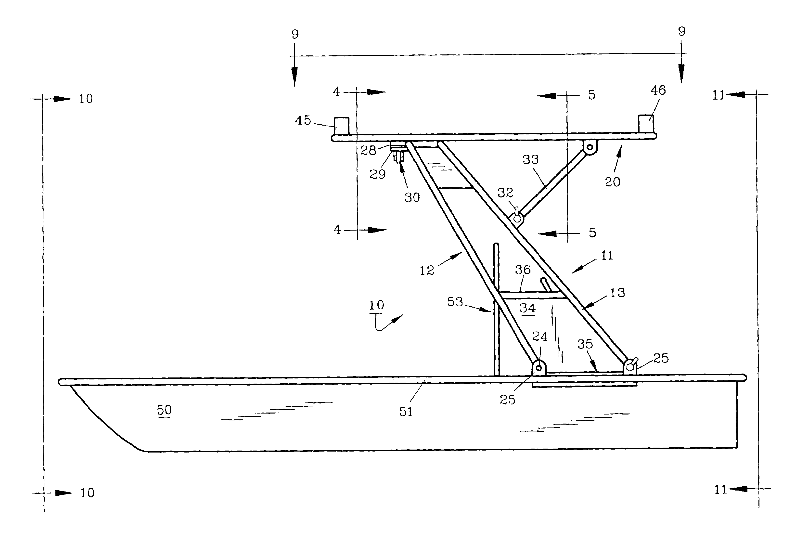
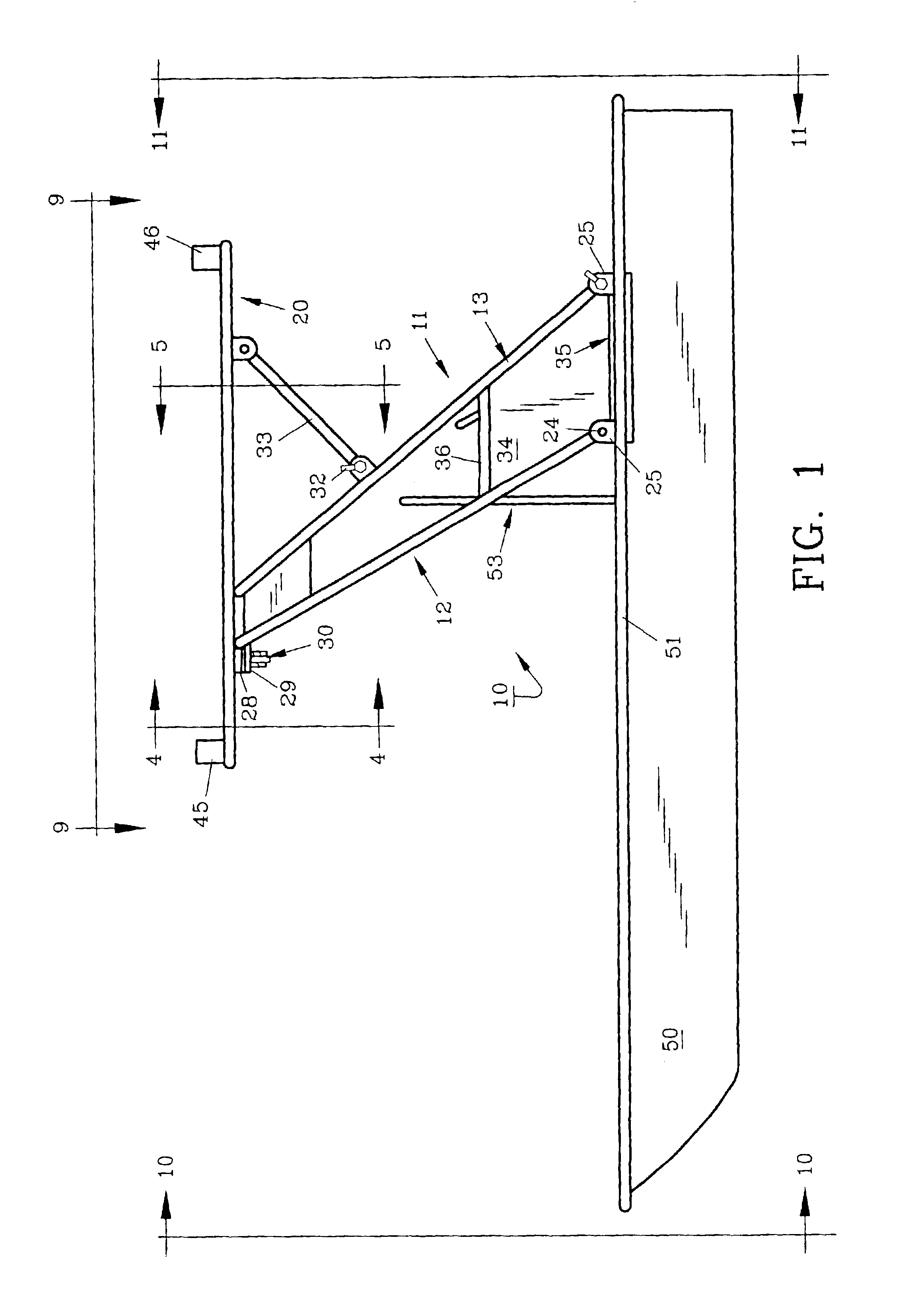
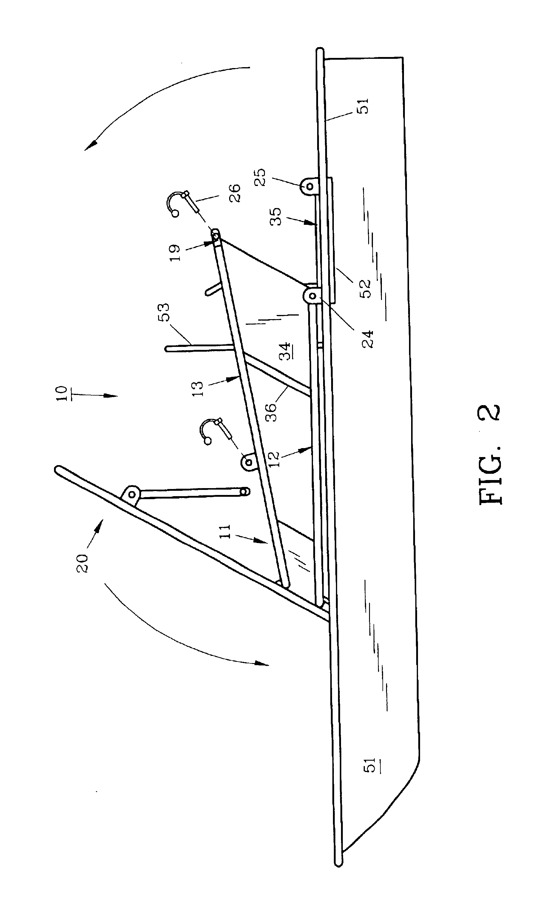
Once erected, to rapidly lower the top, the rear frame member legs on each side of the boat are manually released from the gunwale by removing a locking pin. A pair of shade frame brace pins are also removed, allowing the top to pivot approximately 90.degree. (forward) toward the bow of the boat. By removing a pair of wing nuts which retain bolts which attach the shade frame to the front frame member, the shade frame can then pivot about the rear frame member to allow the shade frame to rest in its dormant position at an acute angle to the horizon below the console windshield. This accommodates the boat's passing under low bridges as needed and easy storage in conventional vehicle garages. The shade frame with its cover to reduce wind resistance by its angle of incidence while in the dormant position when the boat travels at high rates of speed on the water or while being towed behind a vehicle along a highway.
On each side of the boat top, a splash panel having an arm rest is positioned between the tubular frame members. The splash panel helps protect the boat operator from water spray while underway. The side panels can also be used to suspend a fire extinguisher, a small tool cabinet or the like. A gasket placed on each of the gunwales between the tubular members acts as a sealing strip between the splash panel and the gunwale. A storage chest is also provided beneath the shade frame and is attached such as by welding or bolting to the transverse members. The storage chest may contain maps, equipment and the like in a convenient secure, dry manner.

Problems solved by technology

While these tops generally serve the intended purpose they do not offer the protection and sturdiness desired in adverse weather conditions.
In addition, certain conventional boat tops can not remain upright while being towed at highway speeds.
Other standard tops do not provide side spray protection while underway.
Other such tops are bulky, difficult to raise, lower or remove and occupy needed interior space beside the steering console.

Method used


Image

  • Tiltable boat top
  • Tiltable boat top
  • Tiltable boat top

Examples


Embodiment Construction

For a better understanding of the invention and its operation, turning now to the drawings, FIG. 1 demonstrates the preferred form of the invention as shown by tiltable boat top 10 attached by arch 11 to skiff 50. Arch 11, as shown in FIGS. 13, 10 and 11 is affixed to gunwales 51, 51' along each side of skiff 50. To provide support for gunwales 51, 51' wooden gunwale supports 52, 52', such as a conventional 2".times.4" (two by four) are secured to gunwales 51, 51' as by bolts or other standard fasteners (not seen). Arch 11 is also attached to shade frame 20 which is pivoted along with arch 11 as shown in FIGS. 2 and 3.

Shade frame 20 is rectangular in shape as shown in FIG. 9 and is preferably formed of schedule 40 aluminum tubing with a diameter of 11 / 2 inches (3.81 cm). Shade frame cover 21 is lashed to shade frame 20 with standard nylon rope 22 which passes through grommets 23 and around shade frame 20. Shade frame cover 21 is preferably formed of Sunbrella.TM. fabric as manufactu...


PUM


Abstract

A tiltable top is provided for a small boat which allows the boat operator to quickly, manually raise or lower the top as desired. The tiltable top includes a pivotal shade frame and cover which is retained in a normal horizontal position during use or which can be released and allowed to pivot to an acute horizontal angle to lower wind resistence of the boat when the top is lowered.

Description

The present invention pertains to a boat top for use on skiffs and other small boats. The top includes an arch which is affixed to the boat gunwales and has a pivotable shade frame. The top can be tilted from its upright position to a dormant position in a quick, efficient manner.DESCRIPTION OF THE PRIOR ART AND OBJECTIVES OF THE INVENTIONVarious types of tops have been used on small boats in the past as shown in U.S. Pat. Nos. 5,931,114, 6,327,993 and 6,349,666. While these tops generally serve the intended purpose they do not offer the protection and sturdiness desired in adverse weather conditions. In addition, certain conventional boat tops can not remain upright while being towed at highway speeds. Other standard tops do not provide side spray protection while underway. Other such tops are bulky, difficult to raise, lower or remove and occupy needed interior space beside the steering console.Thus, with the problems and disadvantages of prior boat tops, the present invention was...

Claims


Application Information

Patent Timeline
Patent Type & Authority Patents(United States)
IPC IPC(8): B60J7/08B63B17/02B63B17/00
CPCB63B17/02
Inventor WILLIS, D. WAYNE
Owner SMARTOP
Learn More