Rotary parlour for milking of animals

a rotary parlour and animal technology, applied in the field of rotary parlour for milking of animals, can solve the problems of fixed arrangement of dividing members and inability to close the position of cows

Inactive Publication Date: 2004-10-12
DELAVAL HLDG AB
View PDF15 Cites 12 Cited by
  • Summary
  • Abstract
  • Description
  • Claims
  • Application Information

AI Technical Summary

Benefits of technology

This object is achieved by the rotary parlour initially defined, which is characterised in that the centre of the respective feeding trough is located at a distance from a vertical plane extending through the first and second ends of the respective dividing members. The positioning of the feeding troughs at a distance from the dividing members makes it possible for the animals to stand in a natural straight position in the stalls and thus to eat in a convenient manner during the milking operation.
At the same time, the existence of the turnable dividing members enables a close positioning of the animals on the platform.
According to a further embodiment of the invention, each dividing member has an essentially straight extension between the first end and the second end. Thereby, a simple and functional construction of the dividing member is obtained. Preferably, the stalling means is arranged to position the animals in a herringbone pattern along the annular platform. By such an arrangement, the animals may be placed close together on the platform. Certainly, it is possible to use other kinds of arrangement of the animals on the platform in connection with dividing members.
According to a further embodiment of the invention, the rotary parlour comprises an entry and an exit for the animals to and from the platform, respectively. Advantageously, the entry and exit are located at the outer circumference of the platform and located beside each other. Thus, the animals rotate nearly 360.degree. during the milking operation. The entry may have a gate, which is arranged to open periodically in response to the position of the platform and enable entrance of animals to the platform. Preferably, each stall comprises milking means as a cluster. Thus, a simple attachment of the milking means to the animal is obtained.

Problems solved by technology

Fixedly arranged dividing members do not enable a close positioning of the cows on the platform as turnably arranged dividing members.

Method used


Image

  • Rotary parlour for milking of animals
  • Rotary parlour for milking of animals
  • Rotary parlour for milking of animals

Examples


Embodiment Construction

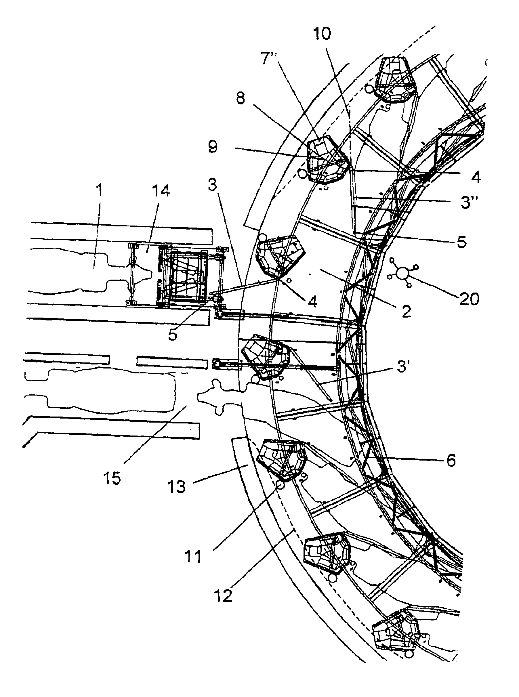
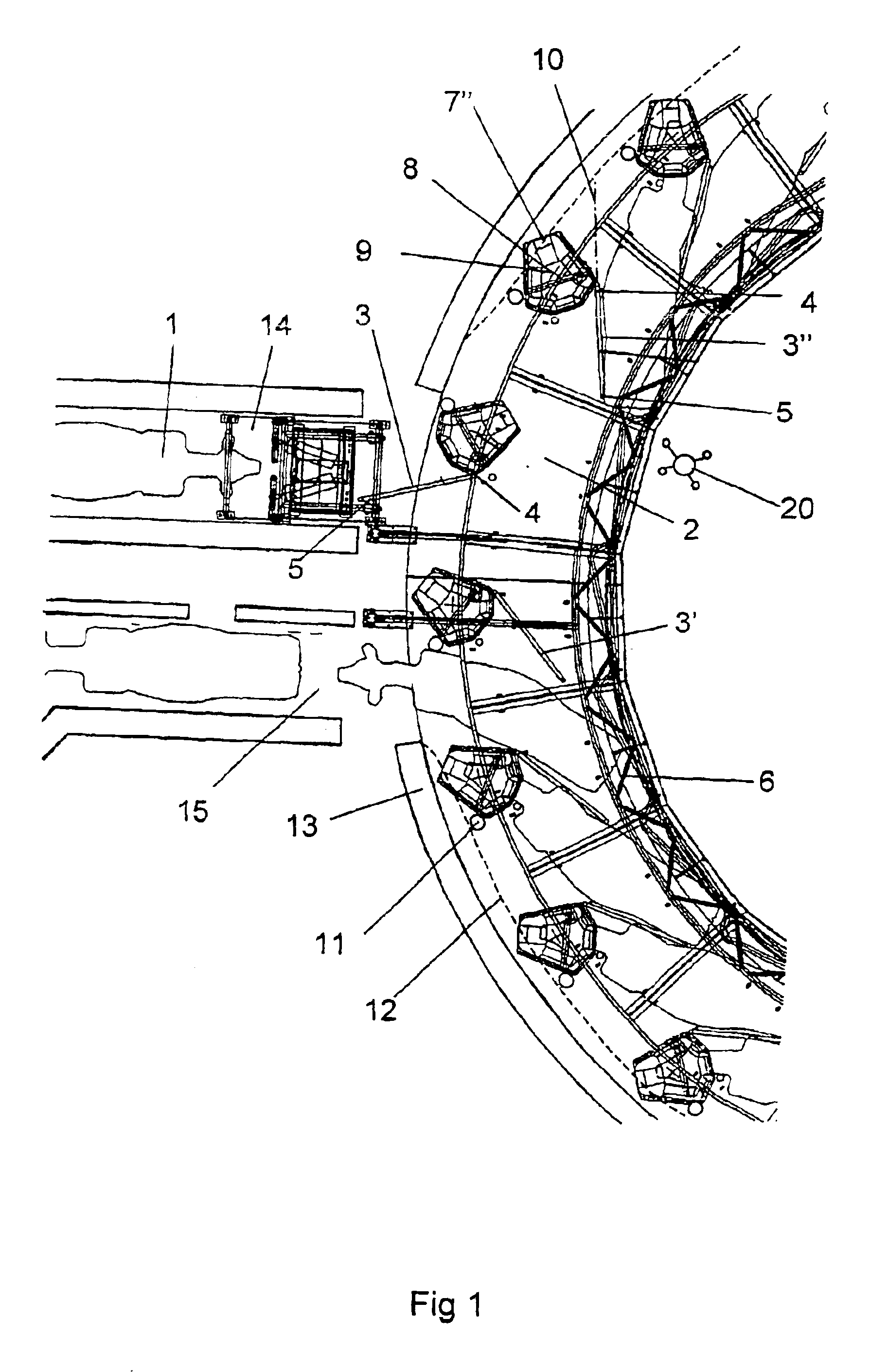
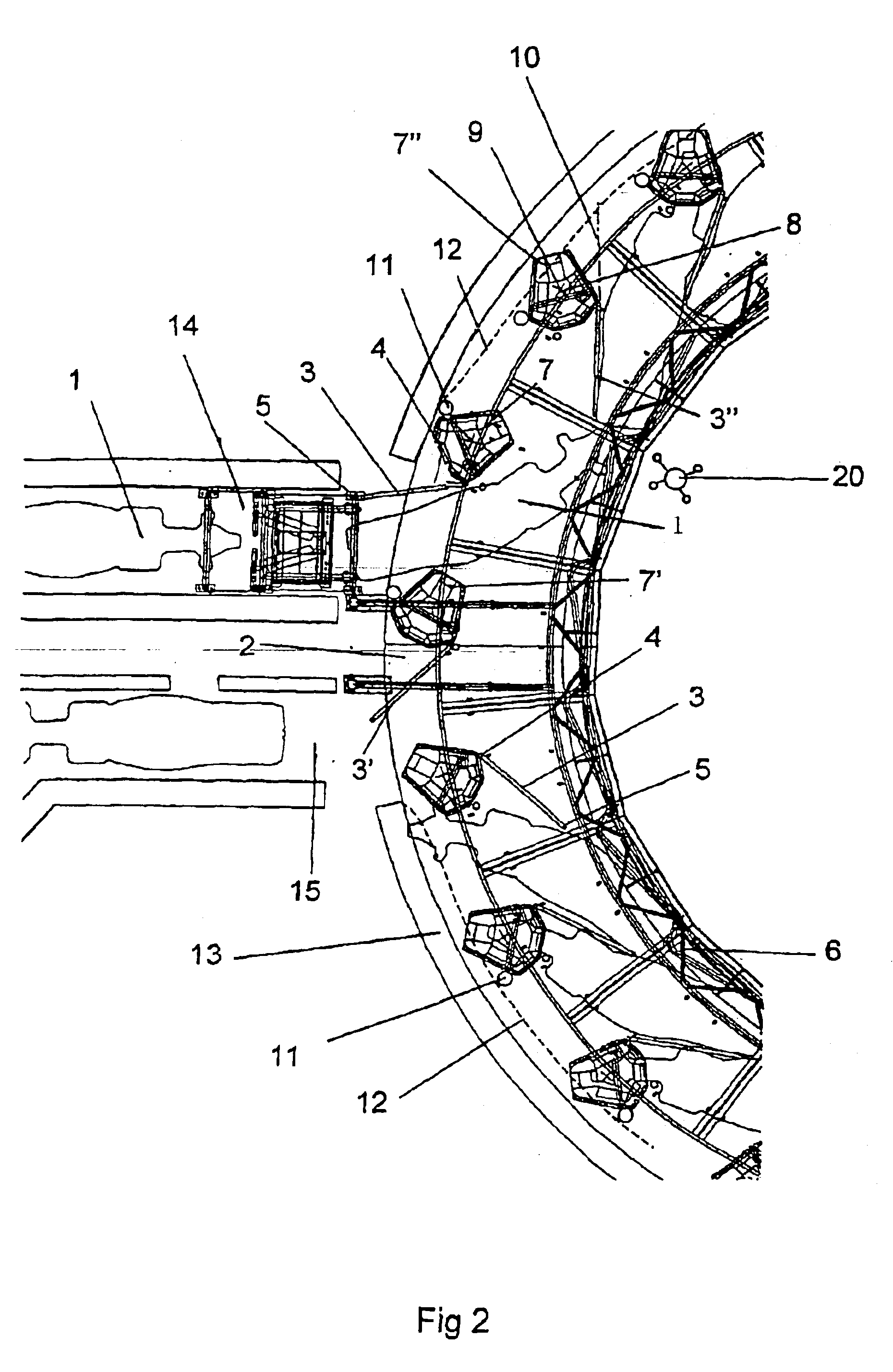
FIGS. 1 and 2 show a rotary parlour for milking of cows 1 from above. The parlour comprises a rotary platform 2 having an annular extension. The platform 2 is arranged to form a support surface for the animals 1. In order to divide the platform 2 into stalls for receiving individual cows 1, stalling means is arranged along the extension of the platform 2. The stalling means comprises dividing members 3 having an essentially straight extension between a first end 4 and a second end 5 and a rumprail 6 arranged at the inner periphery of the platform 2. The stalling means is used to positioning the cows 1 in the respective stalls in a correct position. The rumprail 6 works also as a protection for operators and prevents the cows from accidentally falling or stepping out of the platform 2 into the centre of the parlour. In the stalling position, the cows 1 are positioned in a herringbone pattern along the annular platform 2. The cows 1 face outwards and the operators work from inside of ...


PUM


Abstract

The invention relates to a rotary parlour for milking of animals, especially cows (1). The parlour includes a rotary platform (2) having dividing members (3) arranged to divide the platform (2) into stalls. The dividing members (3) have a substantially straight extension between a first end (4) and a second end (5). The dividing members (3) are each connected to a feeding trough (7) constituting a unit arranged turnably around a vertical axis (8). A center (9) of the feeding trough (7) is located at a distance from a vertical plane (10) extending through the first (4) and second (5) ends of the dividing member (3). By such an arrangement of the feeding trough (7) in relation to the dividing member, it is possible for the animals to stand in a naturally straight position and to eat from the feeding troughs (7) during the milking operation.

Description

THE BACKGROUND OF THE INVENTION AND PRIOR ARTThe present invention relates to a rotary parlour for milking of animals, wherein the parlour comprisesa rotary platform arranged to form a support surface for the animals,stalling means arranged to divide the platform into stalls receiving individual animals, wherein the stalling means comprises dividing members having a first end and a second end and being turnably arranged around a respective vertical axis, wherein the dividing members, in a stalling position, are arranged to be located between adjacent animals with the first end located at a radially outer position in relation to the second end,control means arranged to control the turning of the dividing members around the respective vertical axis and feeding troughs, which each has a centre and is connected to a respective one of the dividing members.Rotary parlours equipped with turnably arranged dividing members are known. By using turnable dividing members, a very close positioni...

Claims


Application Information

Patent Timeline
Patent Type & Authority Patents(United States)
IPC IPC(8): A01K1/12A01K1/00
CPCA01K1/126
Inventor M.ANG.RTENSSON, BENGT-GORAN
Owner DELAVAL HLDG AB
Why Eureka
Try Eureka