Disk device

a technology of a disk and a housing is applied in the field of disk devices, which can solve the problems of thin disk devices, difficult for fine particles to enter the housing, and reduced spacing between respective members

Inactive Publication Date: 2004-11-09
TEAC CORP
View PDF22 Cites 16 Cited by
  • Summary
  • Abstract
  • Description
  • Claims
  • Application Information

AI Technical Summary

Problems solved by technology

Furthermore, spacing between respective members must be reduced so that not only is the disk device thin, but that it will be difficult for fine particles to enter the housing.
In fact, the disk device design should make it difficult for fine particles to adhere on an objective lens such as the optical pick up or an optical part such as a mirror.
The flow of air results in the occurrence of a negative pressure.
Heretofore, there has been a problem with the conventional disk device in that once clamped the upper cover 2 or the tray 5 is bent, the disk 4 clamped by the turn table 6 touches the upper cover 2 due to the occurrence of the above-mentioned negative pressure, so that it is no longer possible to rotate the disk 4 at a constant speed.
On the other hand, if the strengths of the upper cover 2 and the tray 5 are sufficiently enhanced to prevent the upper cover 2 or tray 5 from bending due to the occurrence of the above-mentioned negative pressure, the disk device can not be adequately thinned down to miniaturize the disk device.

Method used


Image

  • Disk device
  • Disk device
  • Disk device

Examples


Embodiment Construction

A description will now be given, with reference to the drawings, of embodiments of the present invention.

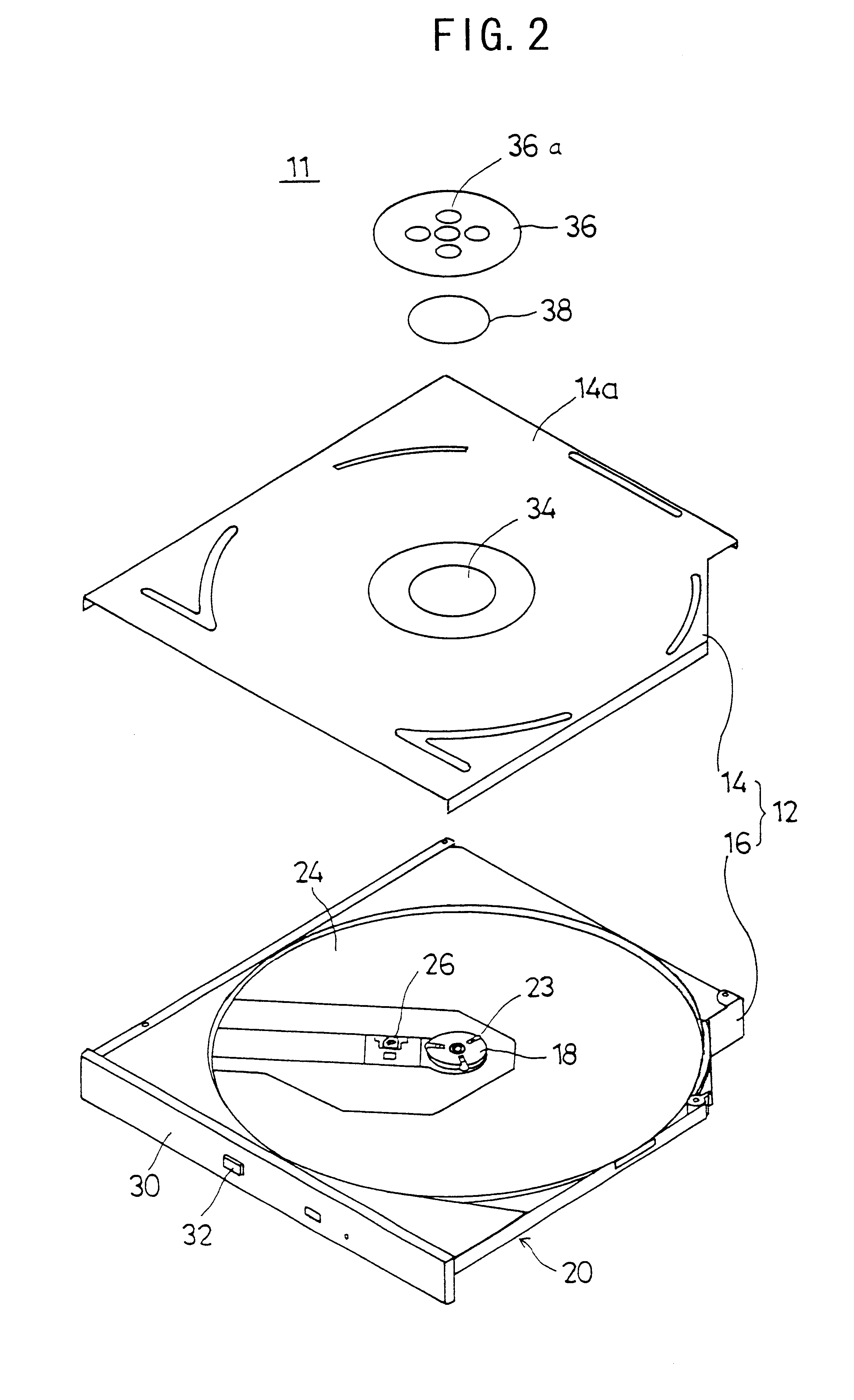
FIG. 2 is an exploded and perspective view showing a first embodiment of a disk device according to the present invention. FIG. 3 is a longitudinal sectional view showing the first embodiment according to the present invention.

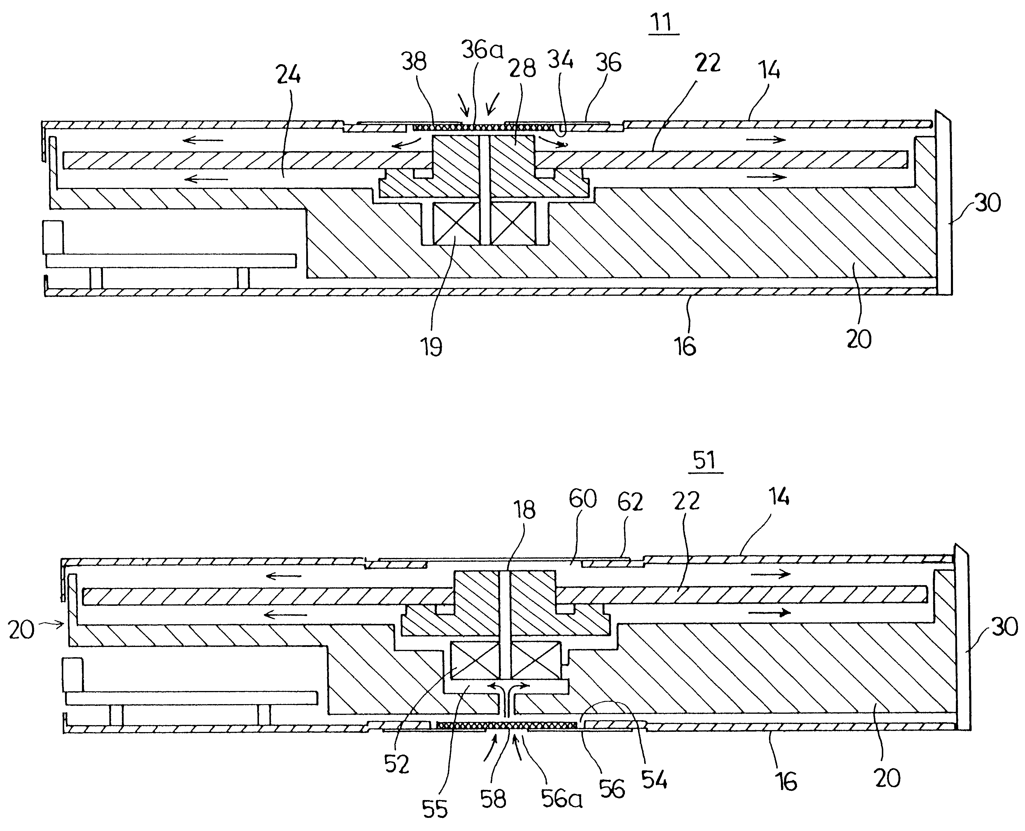
Referring to FIGS. 2 and 3, a disk device 11 includes a tray 20 supporting a turn table 18 in a place between an upper cover 14 and an under cover 16 which form a housing 12. The turn table 18 can be rotated in the above-mentioned place. In the center of the turn table, there is a clamp mechanism 23 clamping a disk 22 so as to engage with an inner circumference of the disk 22. A disk storage part 24 having a diameter bigger than that of the disk 22, is provided around the turn table 18.

A optical pick up 26 is a means for reading out information recorded in the disk 22 clamped by the clamp mechanism 23 of the turn table 18. The optical pick up 26 is arranged...


PUM

PropertyMeasurementUnit
pressureaaaaaaaaaa
structureaaaaaaaaaa
thicknessaaaaaaaaaa

Abstract

A disk device includes a housing in which a disk is provided, a disk support member for supporting the disk in the housing so that the disk can be rotated, and a driving part for rotating the disk support member, wherein the housing includes an air intake part for introducing air to an adjacent place to the disk support member.

Description

1. Field of the InventionThe present invention relates to disk devices, and more particularly, to a disk device for recording or playing back information from a recording medium installed in the disk device.2. Description of the Related ArtIt is desirable to miniaturize a disk device into which a disk-shaped recording medium (hereinafter "disk") such as a CD-ROM is installed for the purpose of equipping a notebook type personal computer with the disk device. To accomplish this, the cover in the housing of the disk device, the tray for supporting the disk, and the housing frame must be thin, compact and relatively strong.Furthermore, spacing between respective members must be reduced so that not only is the disk device thin, but that it will be difficult for fine particles to enter the housing. In fact, the disk device design should make it difficult for fine particles to adhere on an objective lens such as the optical pick up or an optical part such as a mirror.FIG. 1 is a longitudi...

Claims


Application Information

Patent Timeline
Patent Type & Authority Patents(United States)
IPC IPC(8): G11B33/14G11B17/04G11B25/04
CPCG11B33/1486G11B17/056
Inventor MINASE, MINORU
Owner TEAC CORP
Why Eureka
Try Eureka