Method of creating ultra-fine particles of materials using a high-pressure mill

a technology of high-pressure milling and ultra-fine particles, which is applied in the direction of grain milling, centrifuges, solid separation, etc., can solve the problems of crack bifurcation, process relatively inefficient, energy-intensive and inefficient current comminution technology

Inactive Publication Date: 2004-11-30
CORNERSTONE TECH
View PDF41 Cites 77 Cited by
  • Summary
  • Abstract
  • Description
  • Claims
  • Application Information

AI Technical Summary

Problems solved by technology

Thus, current comminution technology is both energy-intensive and inefficient.
Under these conditions, very rapid crack growth is induced and will cause crack bifurcation.
The localized nature of the applied stress and the high energy required for this ultra-fine grinding make this process relatively inefficient.
The low efficiency of existing reduction processes is frequently due to the application of stress where there are no particles.
The result is that much of the energy input is wasted in non-productive contact between, for example, crushing mechanisms or between a crushing mechanism and the mill wall, both of which lower the overall energy efficiency of the process.
Further, for brittle materials, there is a considerable difference between the values of uniaxial compressive strength and tensile strength of the material.
Thus, the chemical processes associated with fracture will significantly affect the energy required to induce this fracture.
The equipment, however, can only operate, at any one time, with small quantities of feed, and the initial feed size of particles lies in the range between 0.5 inches and 50 microns, depending on the type of unit.
A much greater disadvantage for this type of machine is the very high power consumption required to achieve the required crushing.
Under such a situation an analytical approach to coal fragmentation is very complex.
However, with liquid jet comminution, failure occurs on the basis of differential coal porosity and permeability, as these properties control the specific rates of liquid absorption, which directly influence the rate of disintegration.
Conventional comminution technology is both energy intensive and inefficient.
Further, conventional comminution devices are very expensive and wearing process of the friction parts are very significant and costly.
It develops a hydromechanical jet action in these cracks and creates an increasingly dense network of cracks in the walls of the cavity created.

Method used


Image

  • Method of creating ultra-fine particles of materials using a high-pressure mill
  • Method of creating ultra-fine particles of materials using a high-pressure mill
  • Method of creating ultra-fine particles of materials using a high-pressure mill

Examples


first embodiment

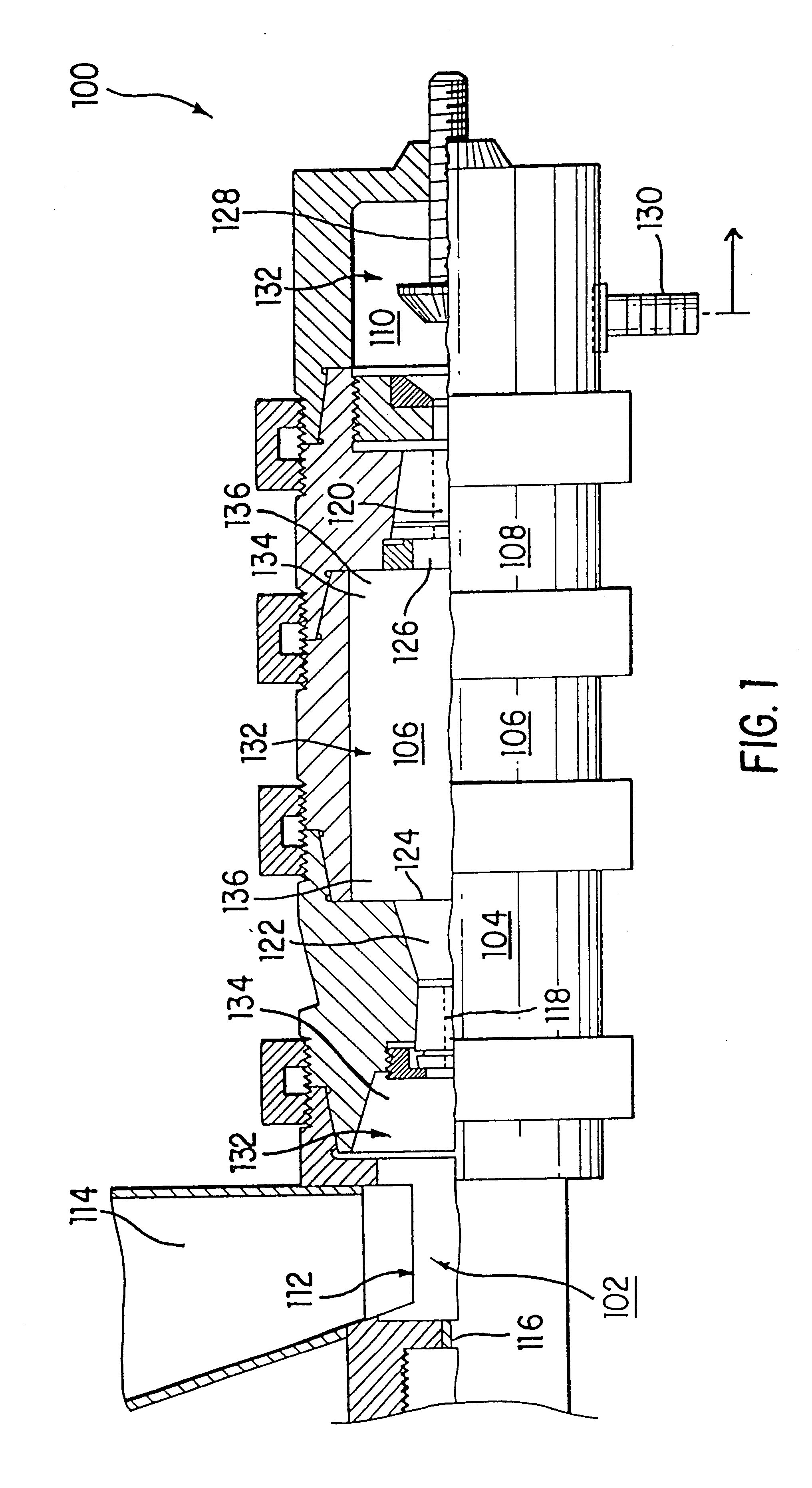
FIG. 1 shows a high-pressure mill 100 for processing materials into ultra-fine particles. Mill 100 includes a first chamber 102, nozzle chambers 104 and 108, a second chamber 106, and a third chamber 110. In one embodiment, chambers 102, 106 and 110 each have a length (measured from inlet to outlet) in the range of 1-20 inches and a diameter in the range of 0.25-10 inches. However, it would be apparent to one skilled in the relevant art that various other sizes and configurations of chambers 102, 106 and 110 could be used to implement mill 100 of the present invention.

First chamber 102 includes an inlet 112. The material to be processed is fed into first chamber 102 via inlet 112. In this embodiment, a funnel 114 is disposed above inlet 112 to facilitate loading of the material to be processed into first chamber 102. In an alternate embodiment, inlet 112 could be connected via a port to an outlet of another similar mill, so that the particles exiting a first mill could be pumped int...

example

FIG. 8 shows a graph of particle size distribution resulting from use of the mill of the present invention for processing anthracite. In this example, the distribution marked as 802 is based on a feed size of 0.25-0.5 inches. For the distribution marked as 804, the feed size was 0.02-0.05 inches. The test mill included first chamber 102, nozzle chamber 104, second chamber 106 and third chamber 110, as described above with respect to mill 100. The nozzle for high pressure fluid jet 116 had a diameter of 0.012 inches and the primary slurry nozzle of nozzle chamber 104 was 0.045 inches. The fluid pressure for jet 116 used for the particles shown in distribution 802 was 40,000 psi, and the fluid pressure for jet 116 used for the particles shown in distribution 804 was 30,000 psi. Collider 128 in third chamber 110 was in a fully open position.

As shown in the graphs of FIG. 8, for a feed size of 0.25-0.5 inches, the mill of the present invention comminuted approximately 90% of these start...


PUM

PropertyMeasurementUnit
sizeaaaaaaaaaa
sizeaaaaaaaaaa
pressureaaaaaaaaaa

Abstract

A method for creating ultra-fine particles of material using a high-pressure mill is described. The method includes placing a material in a first chamber and subjecting the material to a high-pressure fluid jet to divide it into particles. These particles are then transferred to a second chamber in which they are subjected to cavitation to further divide the particles into relatively smaller particles. These relatively smaller particles are then transferred to a third chamber, in which the particles collide with a collider to still further divide them into ultra-fine particles of the material. The mill of the present invention includes a first chamber having an high-pressure liquid jet nozzle, first and second slurry nozzles, a second cavitation chamber and a third chamber which houses a collider. In one embodiment, the slurry nozzle has an inner surface and sharp edges that project slightly out from the inner surface. Sensors may be located throughout the mill to collect data on the comminution process and to use the data to control the resultant particle size. The product size of the ultra-fine particles made according to the mill of the present invention are preferably less than 15 microns. Further, the particles produced using the mill of the present invention are formed as flakes or platelets which have been broken along nature planes in the material.

Description

1. Field of the InventionThe present invention relates to a method for creating ultra-fine particles of a material using high-pressure fluid. More particularly, the present invention relates to a method for subjecting particles to a high-pressure fluid jet, high turbulence condition, cavitation and collision to comminute the particles.2. Related ArtComminution may be defined as either a single or multistage process by which material particles are reduced from random sizes by crushing and grinding to the size required for the intended purpose.Size reduction in comminution machines relies on three different fragmentation mechanisms: cleavage, shatter, and abrasion. It is commonly stated that only three percent of the energy used in fragmenting solid particles goes into the creation of new surfaces. Thus, current comminution technology is both energy-intensive and inefficient.During milling of material, to create a fracture in the particles of material, a stress must be induced which e...

Claims


Application Information

Patent Timeline
Patent Type & Authority Patents(United States)
IPC IPC(8): B02C19/06
CPCB02C19/06B02C19/066B02C19/065
Inventor MAZURKIEWICZ, MARIANCONRAD, BRUCE E.
Owner CORNERSTONE TECH
Why Eureka
Try Eureka