Data transmission in a telecommunications network

a data transmission and telecommunications network technology, applied in data switching networks, wireless commuication services, multiplex communication, etc., can solve the problems of inability to send data, and the backlog of unsent data may build up for the input flow

Inactive Publication Date: 2004-11-30
TELEFON AB LM ERICSSON (PUBL)
View PDF5 Cites 52 Cited by
  • Summary
  • Abstract
  • Description
  • Claims
  • Application Information

AI Technical Summary

Problems solved by technology

This is not possible in UMTS, as UMTS relies upon Transport Format Combinations Sets (TFCSs) as the basic mechanism defining how much data can be sent in each transmission time interval.
In the former case, a backlog of unsent data may build up for the input flow.

Method used


Image

  • Data transmission in a telecommunications network
  • Data transmission in a telecommunications network
  • Data transmission in a telecommunications network

Examples


Embodiment Construction

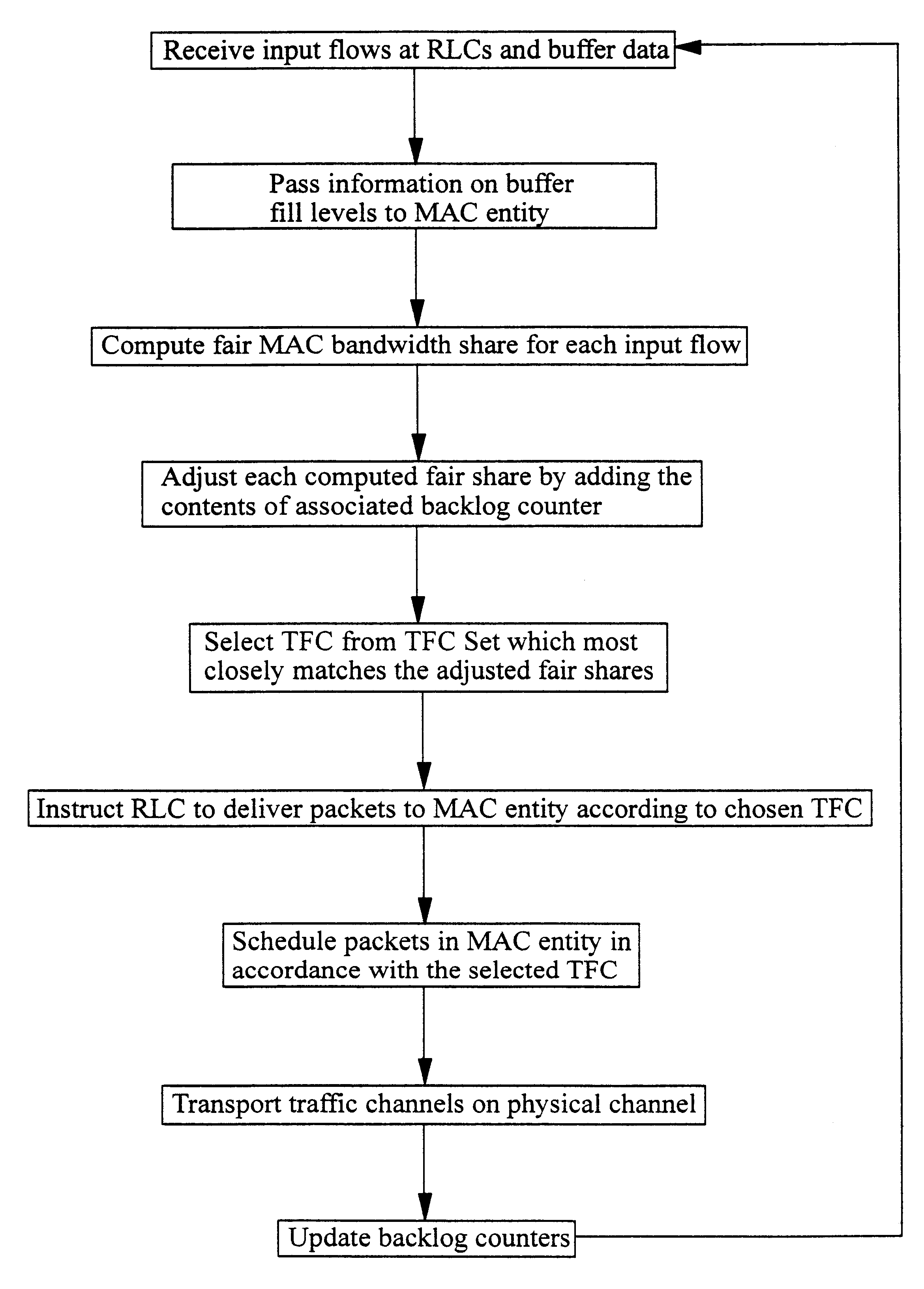
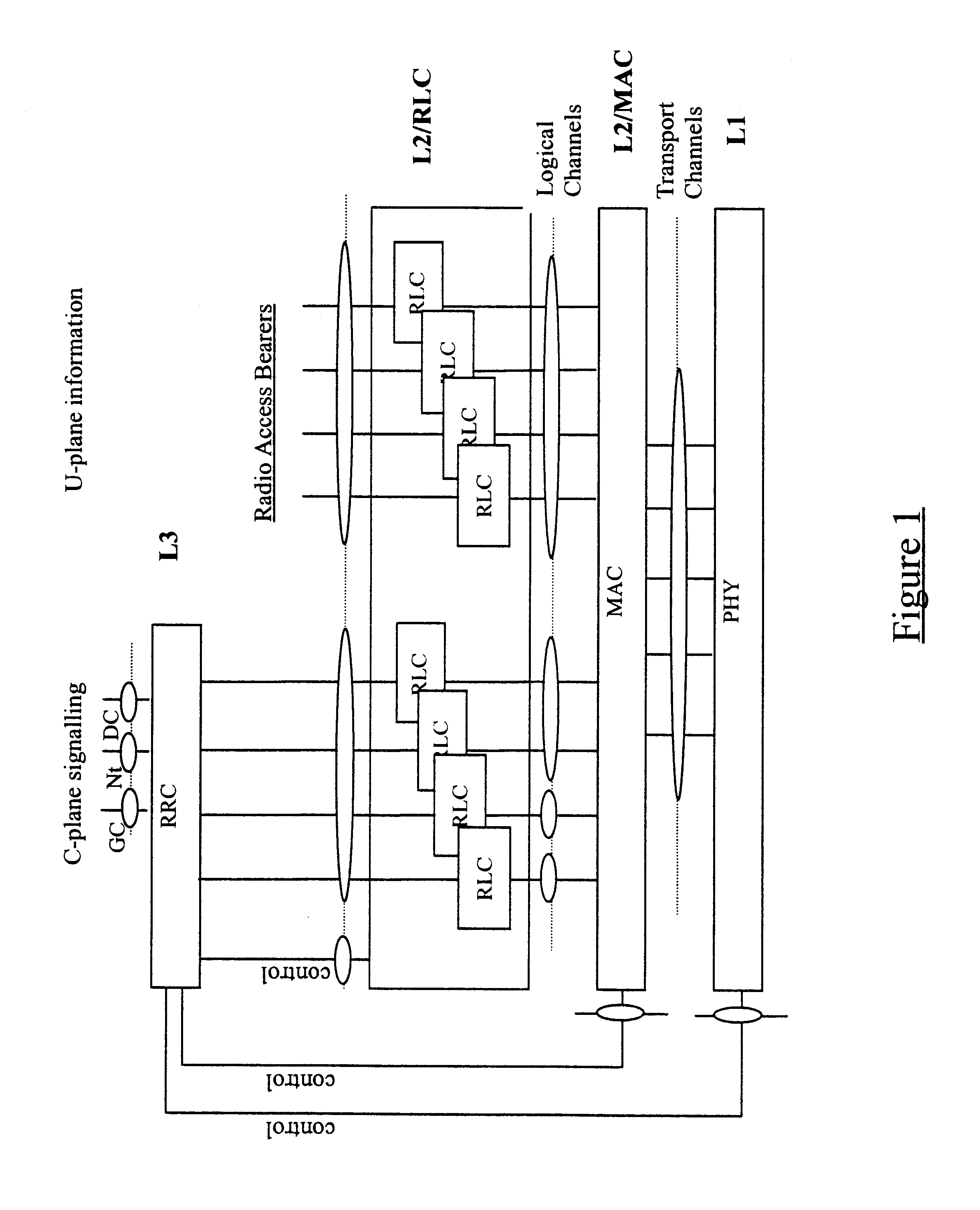
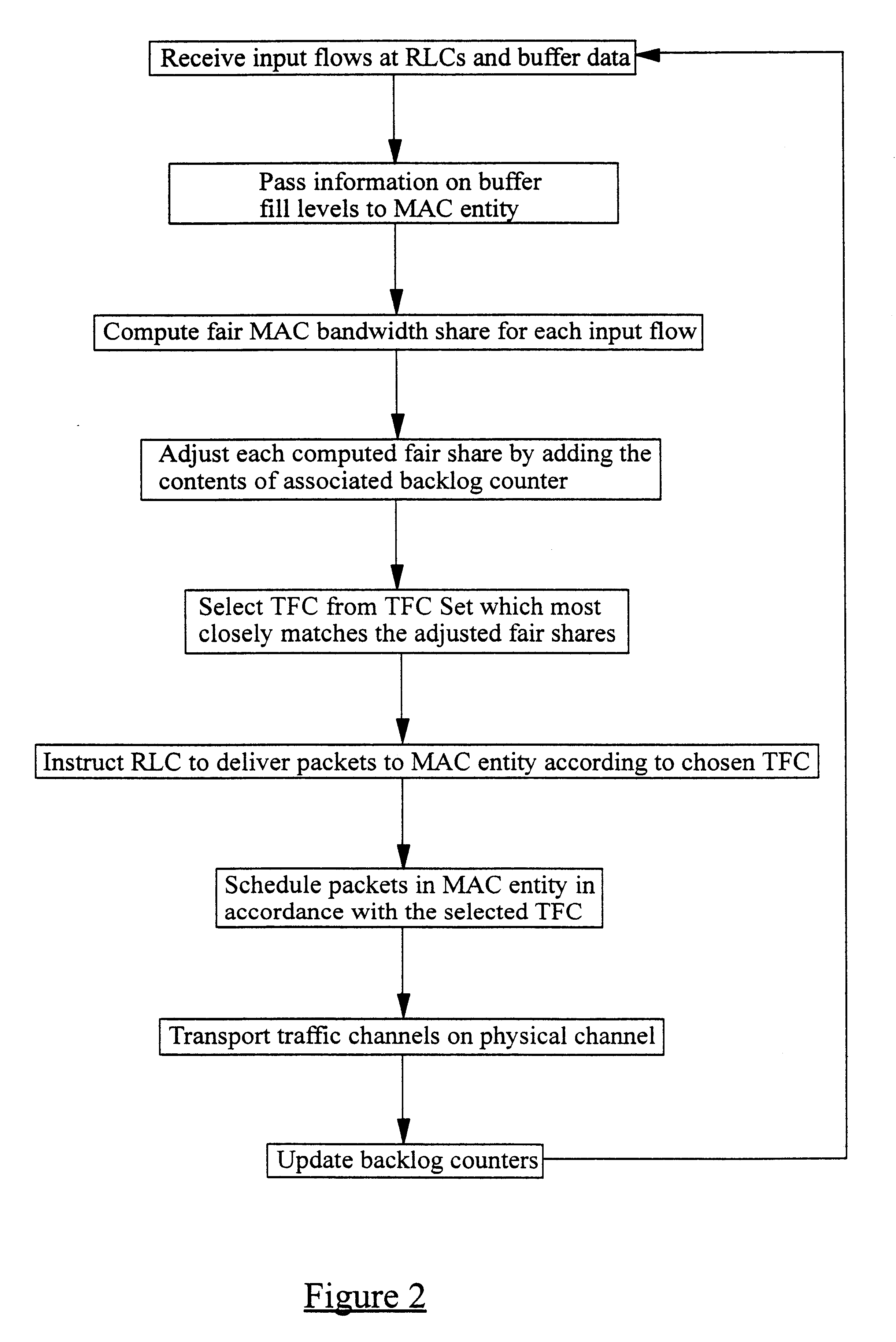
As has already been described above, a simplified UMTS layer 2 consists of one Radio Resource Control (RRC) entity, a Medium Access Control (MAC) entity for each mobile station, and a Radio Link Control (RLC) entity for each Radio Access Bearer (RAB). The MAC entity performs scheduling of outgoing data packets, while the RLC entities provide buffers for respective input flows. The RRC entity sets a limit on the maximum amount of data that can be transmitted from each flow by assigning a set of allowed Transport Format Combinations (TFC) to each MAC (referred to as a TFC Set or TFCS), but each MAC must independently decide how much data is transmitted from each flow by choosing the best available Transport Format Combination (TFC) from the TFCS.

The proposed method works by calculating at the MAC entity, (on a per Transmission Time Interval basis) the optimal distribution of available bandwidth using the Generalised Processor Sharing GPS approach (see the article by A. K. Parekh et al...


PUM


Abstract

A method of allocating transmission resources at a Media Access Control (MAC) entity of a node of a Universal Mobile Telecommunications System (UMTS). The method comprises, for each frame of an output data flow, computing for each input flow to the MAC entity a fair share of the available output bandwidth of the MAC entity. A Transport Format Combination (TFC) is then identified from a TFC Set (TFCS) on the basis of the bandwidth shares computed for the flows, where the TFC comprises a Transport Format allocated to each input flow. For each input flow, if the allocated TF results in a data transmission rate which is less than the determined fair distribution, the difference is added to a backlog counter for the input flow. The value of the backlog counters is taken into account when selecting a TFC for the subsequent frame of the output data flow.

Description

The present invention relates to data transmission in a telecommunications network and in particular, though not necessarily, to data transmission in a Universal Mobile Telecommunications System (UMTS).BACKGROUND TO THE INVENTIONThe European Telecommunications Standardisation Institute (ETSI) is currently in the process of standardising a new set of protocols for mobile telecommunications systems. The set of protocols is known collectively as the Universal Mobile Telecommunications System (UMTS). FIG. 1 illustrates a simplified UMTS layer 2 protocol structure which is involved in the communication between mobile stations (e.g. mobile telephones) and Radio Network Controllers (RNCs) of a UMTS network. The RNCs are analogous to the Base Station Controllers (BSCs) of existing GSM mobile telecommunications networks, communicating with the mobile stations via Base Transceiver Stations (BTS).The layer 2 structure of FIG. 1 consists of a set of Radio Access Bearers (RABs) which make availa...

Claims


Application Information

Patent Timeline
Patent Type & Authority Patents(United States)
IPC IPC(8): H04Q7/38H04L12/28H04L12/56H04W28/08H04W28/10H04W72/04H04W84/04
CPCH04W72/0453H04W28/08H04W28/10H04W84/04H04W72/00
Inventor PEISA, JANNE
Owner TELEFON AB LM ERICSSON (PUBL)
Why Eureka
Try Eureka