Method and apparatus for estimating water bottom reflection time difference

a technology of time difference and water bottom, applied in the field of marine seismic surveying, can solve the problems of survey suspension, reduced survey accuracy, and difficulty in analyzing the combined seismic data s

Inactive Publication Date: 2004-11-30
WESTERNGECO LLC
View PDF2 Cites 15 Cited by
  • Summary
  • Abstract
  • Description
  • Claims
  • Application Information

AI Technical Summary

Problems solved by technology

Consequently, the variations in the travel times may make it difficult to analyze the combined seismic data set and may reduce the accuracy of the survey.
For another example, inclement weather and / or high seas may force a survey to be suspended before resuming hours or days later.
Combining data from different times, and especially from different surveys, may exacerbate the aforementioned difficulties associated with variations in the velocity of sound in the water layer.
For another example, shifts in water currents may cause unpredictable variations in the velocity of sound in water, particularly for surveys carried out near the edge of strong water currents.
One problem with this method is that the velocity analysis must be extremely accurate.
Another issue is the effect of water bottom structure on the velocity analysis.
If the dip of the water bottom (the angle the water bottom makes with a horizontal plane) changes between or along sail lines, the calculated velocities are strongly affected and may reduce the accuracy of the .DELTA.t calculation.
One difficulty with this method is that the averaged pick times are affected by the difference between the actual normal move-out and the approximate normal move-out applied to correct the pick times. The effect of these differences propagates into the delta-t values.
Furthermore, the iteration procedures used in this method are difficult to apply in practice.

Method used


Image

  • Method and apparatus for estimating water bottom reflection time difference
  • Method and apparatus for estimating water bottom reflection time difference
  • Method and apparatus for estimating water bottom reflection time difference

Examples


Embodiment Construction

Illustrative embodiments of the invention are described below. In the interest of clarity, not all features of an actual implementation are described in this specification. It will of course be appreciated that in the development of any such actual embodiment, numerous implementation-specific decisions must be made to achieve the developers' specific goals, such as compliance with system-related and business-related constraints, which will vary from one implementation to another. Moreover, it will be appreciated that such a development effort might be complex and time-consuming, but would nevertheless be a routine undertaking for those of ordinary skill in the art having the benefit of this disclosure.

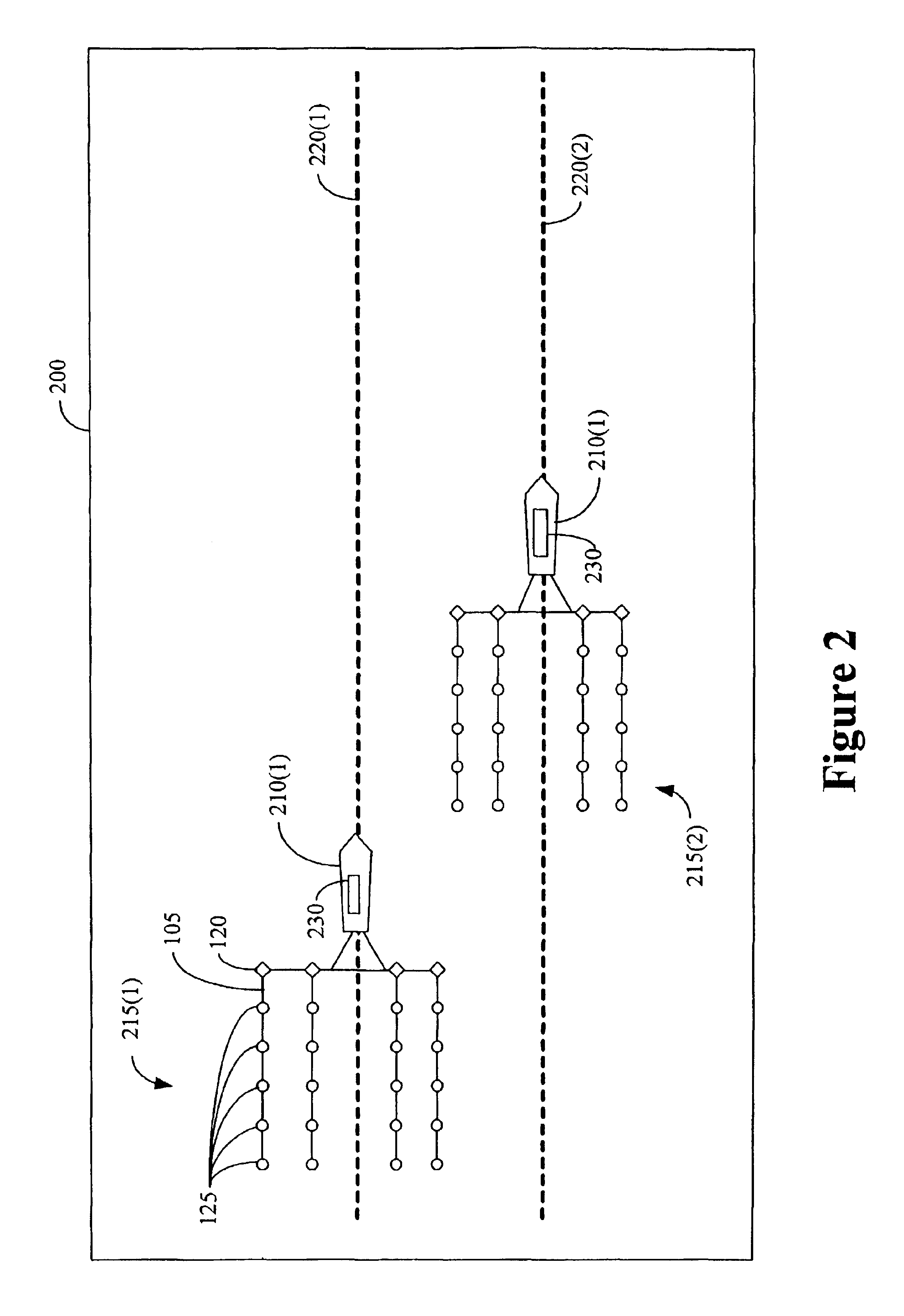
FIG. 2 conceptually illustrates a marine seismic survey area 200. To survey the marine seismic survey area 200, one or more survey vessels 210(1-2) tow one or more seismic arrays 215(1-2) over the marine seismic survey area 200. It will also be appreciated that, while the survey vessel...


PUM


Abstract

The present invention provides a method for reducing water bottom reflection time differences. The method includes selecting a plurality of trace groups, each trace having an offset from a midpoint and a water bottom reflection time. The method also includes determining a rate of change of the water bottom reflection time of each trace and generating a model water velocity and a model water bottom reflection time for each trace midpoint using a preselected function of the water bottom reflection times and the rates of change. Furthermore, the method includes generating a plurality of water bottom reflection time corrections for the traces in each trace group using a pre-selected function of the water bottom reflection times, the model water bottom reflection times, the model water velocities, and the trace offsets.

Description

1. Field of the InventionThis invention relates generally to marine seismic surveying, and, more particularly, to estimating water bottom time differences in marine seismic surveying.2. Description of the Related ArtSeismic exploration is widely used to locate and / or survey subterranean geological formations for hydrocarbon deposits. Since many commercially valuable hydrocarbon deposits are located beneath bodies of water, various types of marine seismic surveys have been developed. In a typical marine seismic survey, such as the exemplary survey conceptually illustrated in FIG. 1, an array 100 of marine seismic streamer cables 105 is towed behind a survey vessel 10 over a survey area 115. The seismic streamer cables 105 may be several thousand meters long and contain a large number of sensors 125, such as hydrophones and associated electronic equipment, which are distributed along the length of the each seismic streamer cable 105. The survey vessel 110 also tows one or more seismic...

Claims


Application Information

Patent Timeline
Patent Type & Authority Patents(United States)
IPC IPC(8): G01V1/28G01V1/36
CPCG01V1/362G01V2210/52G01V1/38
Inventor CARVILL, CHARLES V.
Owner WESTERNGECO LLC
Why Eureka
Try Eureka