Methods and apparatus for improved hydropower system

a hydrokinetic power system and hydroelectric technology, applied in the direction of electric generator control, couplings, fluid couplings, etc., to achieve the effect of improving the hydrokinetic power system, reducing the loss of flow velocity, and increasing the flow velocity

Inactive Publication Date: 2008-07-31
HYDRO GREEN ENERGY LLC
View PDF11 Cites 8 Cited by
  • Summary
  • Abstract
  • Description
  • Claims
  • Application Information

AI Technical Summary

Benefits of technology

[0007]The primary advantage of the invention is to provide improved hydrokinetic power system.
[0008]Another advantage of the invention is to provide a retrofit for existing dams to increase velocity of flow to a kinetic power system.
[0009]Another advantage of the invention is a method to retrofit existing hydropower dam system outflow draft tubes to lessen the loss of flow velocity to improve efficiency and increase power in downstream hydrokinetic turbines.
[0010]Another advantage of the invention is to provide wall system to channel flow to increase kinetic energy downstream of a dam for a hydrokinetic power system.
[0011]A further advantage of the invention is to provide a kinetic power system that utilizes increase flow dynami...

Problems solved by technology

One of the current problems facing hydrokinetic power producers when locating hydrokinetic turbines downstream of existing dams is that the design of the draft tube at an existing dam (the draft tube conducts water from the outlet of the turbine to the body of water downstream of the existing dam) is specifically designed to d...

Method used


Image

  • Methods and apparatus for improved hydropower system
  • Methods and apparatus for improved hydropower system
  • Methods and apparatus for improved hydropower system

Examples


Embodiment Construction

[0023]Detailed descriptions of the preferred embodiment are provided herein. It is to be understood, however, that the present invention may be embodied in various forms. Therefore, specific details disclosed herein are not to be interpreted as limiting, but rather as a basis for the claims and as a representative basis for teaching one skilled in the art to employ the present invention in virtually any appropriately detailed system, structure or manner.

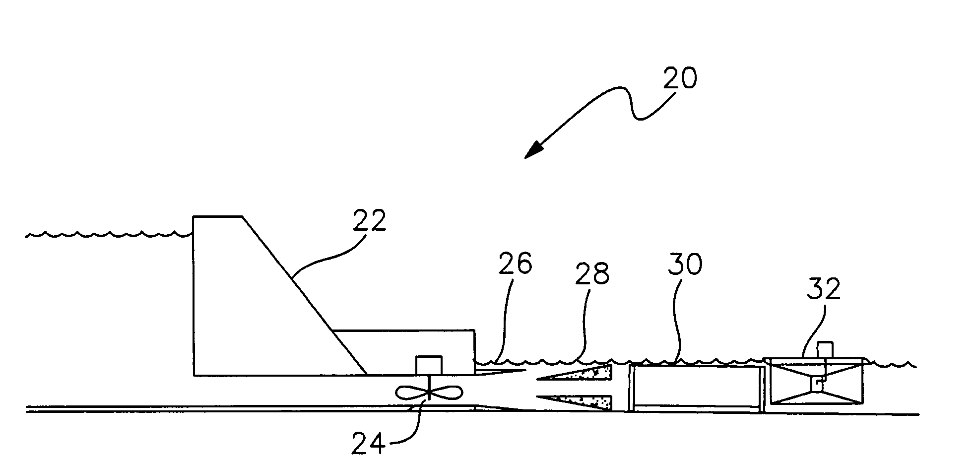
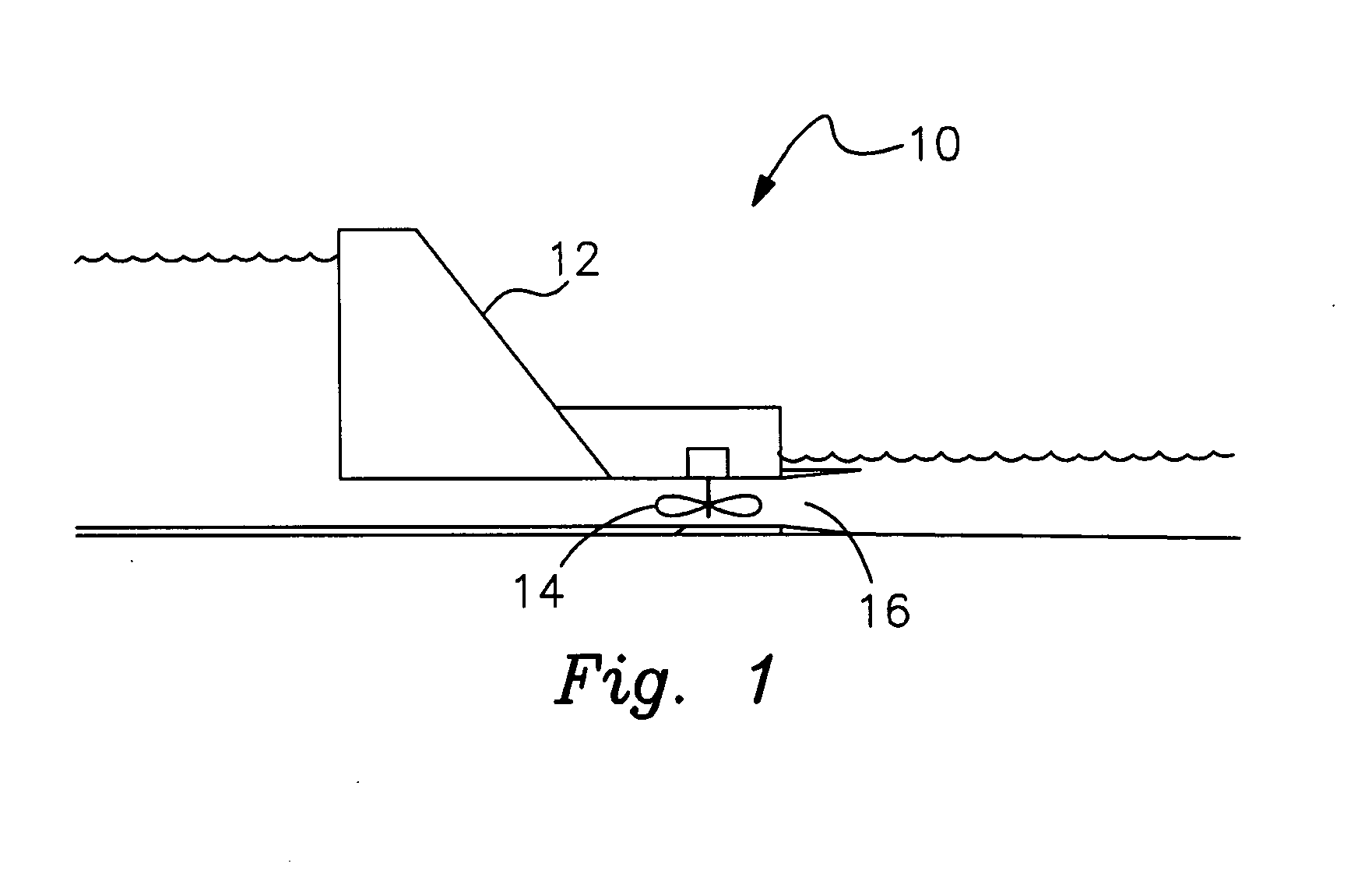
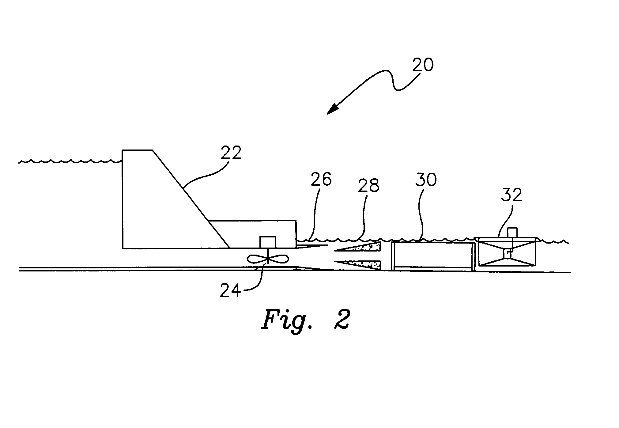
[0024]A system to retrofit existing hydropower dams so that the kinetic energy in the tailrace (the tailrace is the body of water directly at the outlet of the draft tube) can be increased for higher hydrokinetic energy production at a downstream hydrokinetic energy generating power station. FIG. 1 shows a conventional power system 10 where head power from the upstream water blocked by a dam 12 is used to drive turbine 14 to generate power. Outflow of turbine 14 is through draft tube 16 which dissipates the flow of water from the tur...


PUM


Abstract

Methods and apparatus for improved power generation through movement of water retrofitting existing hydroelectric dams with draft tube inserts and tailrace walls to increase water velocity for production of power using hydrokinetic turbines installed in the tailrace. By initial design or by draft tube inserts and tailrace walls, increased and streamlined water flow leads to higher efficiencies of the hydrokinetic turbine, thus more efficiently converting available kinetic energy of the water into usable energy.

Description

CROSS REFERENCE TO RELATED APPLICATIONS[0001]This application is based on provisional application Ser. No. 60 / 859,789, filed on Nov. 17, 2006, which is incorporated as if fully set forth herein.STATEMENT REGARDING FEDERALLY SPONSORED RESEARCH OR DEVELOPMENT[0002]Not ApplicableDESCRIPTION OF ATTACHED APPENDIX[0003]Not ApplicableBACKGROUND OF THE INVENTION[0004]This invention relates generally to the field of energy and more specifically to methods and apparatus for an improved hydropower system.[0005]There are a variety of prior art systems for extracting power from water based systems such as dams, rivers and ocean flows. Several patents disclose a variety of after market retrofits for extracting hydropower from river flow by inserting additional equipment at the base of the dam to take advantage of the head potential present behind the dam. For example, U.S. Pat. Nos. 4,073,146, 4,078,388, 4,117,676, 4,159,188, 4,165,467, 4,170,428, 4,261,171, 4,279,539, and 4,468,153 show a retrof...

Claims


Application Information

Patent Timeline
IPC IPC(8): F03B13/08
CPCY02E10/22F03B13/08Y02E10/20
Inventor KROUSE, WAYNE F.
Owner HYDRO GREEN ENERGY LLC
Why Eureka
Try Eureka