Pneumatic fastener driving tool for hardwood flooring

a technology of pneumatic flooring and driving tools, which is applied in the direction of manufacturing tools, nailing tools, stapling tools, etc., can solve the problems of reducing the service life of pneumatic flooring tools, consuming excessive quantities of compressed air, and slowing down the reload speed of tools, so as to reduce labor costs, improve the reload speed of pneumatic tools, and reduce maintenance time

Active Publication Date: 2004-12-28
LABE PRIMATECH
View PDF18 Cites 32 Cited by
  • Summary
  • Abstract
  • Description
  • Claims
  • Application Information

AI Technical Summary

Benefits of technology

Another object of the invention is to improve upon reload speed of the pneumatic tool.
A further object of the invention is to reduce labour costs and reducing maintenance time by facilitating fast and easy access via t...

Problems solved by technology

In prior art tools of this type, movement synchronisation between all mobile parts within the fastener discharge mechanism lacks optimization, which results in a slower reload speed of the tool.
Furthermore, ac...

Method used


Image

  • Pneumatic fastener driving tool for hardwood flooring
  • Pneumatic fastener driving tool for hardwood flooring
  • Pneumatic fastener driving tool for hardwood flooring

Examples


Embodiment Construction

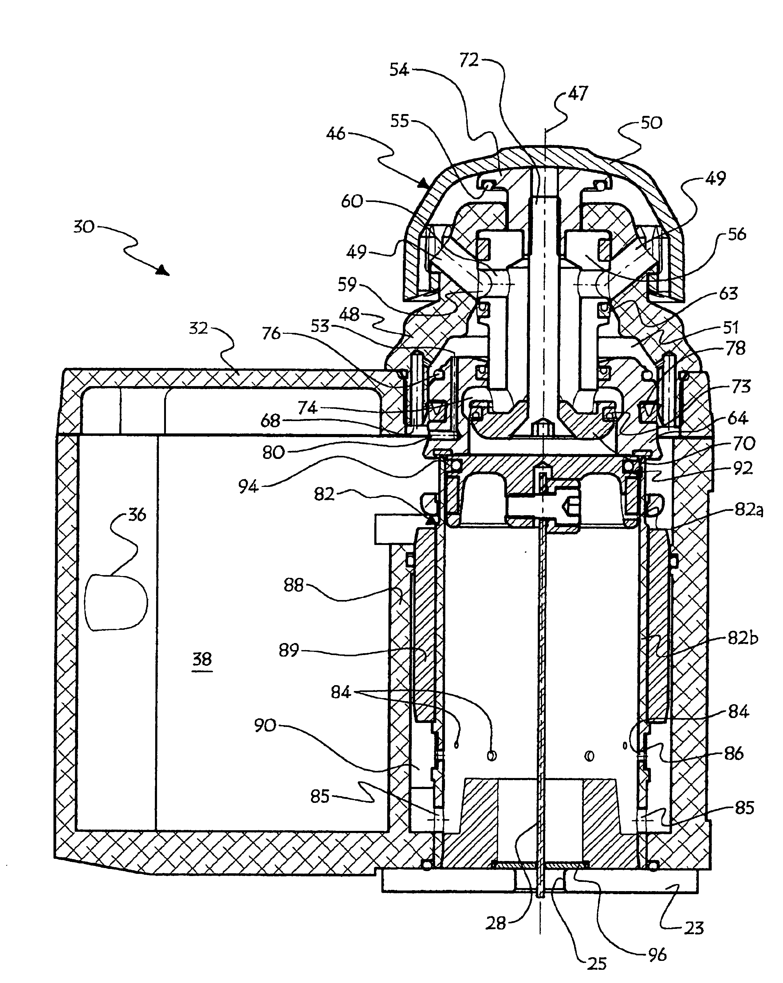
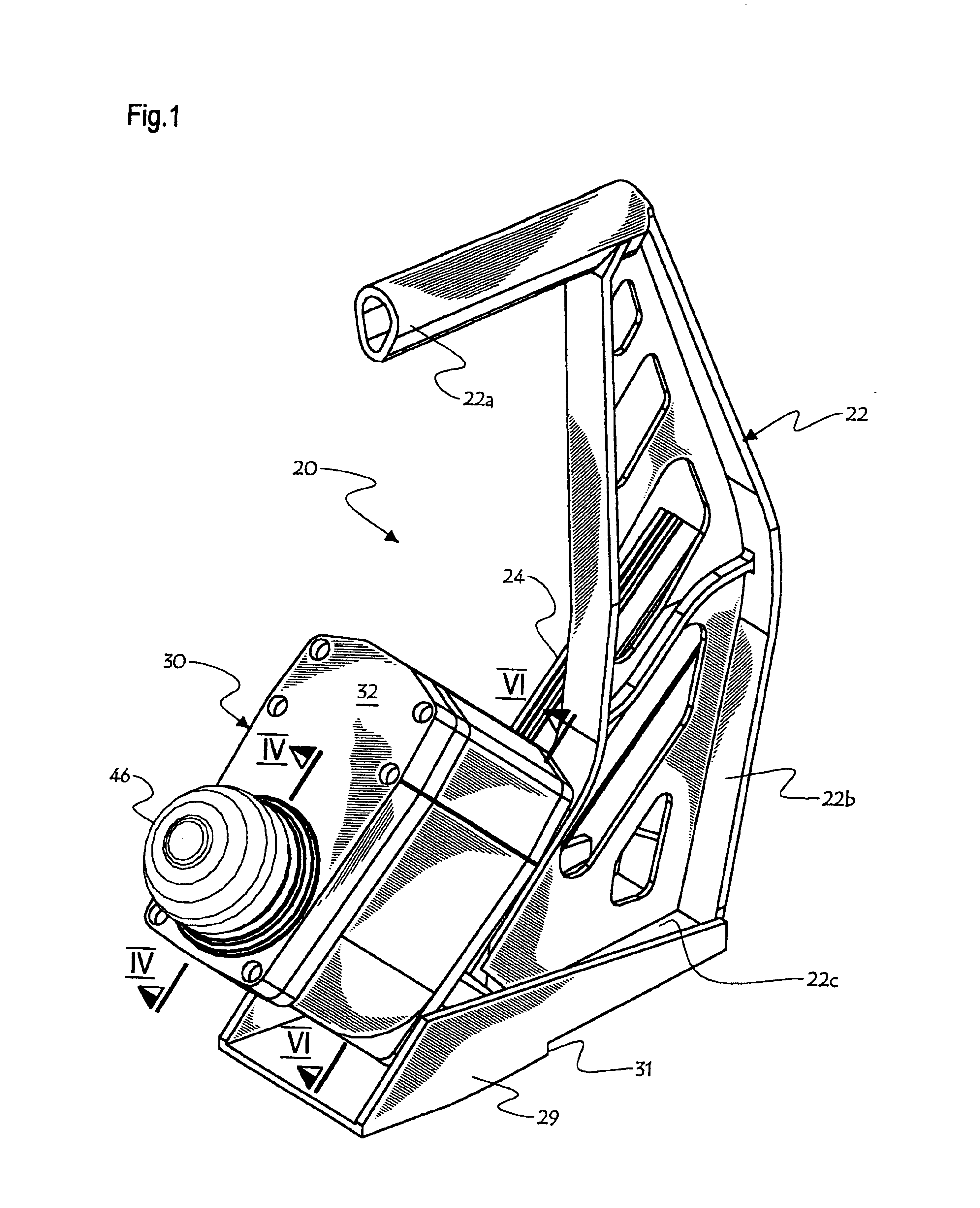
FIGS. 1-2 generally show a pneumatic mallet-operated fastener driving tool 20 according to the present invention, used for securing hardwood planks to a subfloor.

Tool 20 comprise a G-shaped frame 22, made of a one-piece moulded metal for example, defining a handle portion 22a integrally attached to one end of an arm portion 22b, which integrally carries an elbowed baseplate 22c at its other end. Elbowed baseplate 22c integrally carries an attachment plate 22d. A fastener feeder in the form of an elongated magazine 24 is affixed to one side of frame arm 22b in a rearwardly upwardly sloped fashion, and is for holding a supply of fasteners, e.g. a strip of metallic L- or T-shaped barb-provided cleats commonly used in floor assembling duties. A launch plate 26 (concealed in FIG. 1, but shown in FIG. 2), made from an assembly of two plates for ease of manufacture purposes, is affixed to the bottom surface of elbowed baseplate 22c perpendicularly to elongated magazine 24. Magazine 24 comp...


PUM


Abstract

A pneumatic mallet-blow operated fastener driving tool for securing hardwood planks to a subfloor, which comprises a fastener discharge mechanism in turn comprising a housing having a pressurized main chamber in direct link with a compressed air intake, a selectively depressurizable closure chamber pressurized when the tool is at rest, and a cylinder in which a piston having a plunger affixed thereto is slidably mounted. A valve, biased toward a closed position when the closure chamber is pressurized, or biased towards its open limit position if the closure chamber is depressurized, permits selective establishment of fluid communication between the inside of the cylinder and the pressurized main chamber. The piston, at a retracted limit position when the tool is at rest, is forced towards a deployed limit position when fluid communication is established between the main chamber and the inside of the cylinder, in order for its plunger to strike a fastener and drive it into an underlying plank. In use, after the mallet blow has engendered depressurizing of the closure chamber, the valve is moved in its open limit position, a fastener is discharged from the tool upon being struck by deployment of the piston by being struck by its plunger, and closure chamber starts to become pressurized again by compressed fluid flowing therein from the main chamber through a first fluid inlet, which initiates movement of the valve towards its closed position, and after such movement is initiated, a second fluid inlet port opens up to further admit compressed air into the closure chamber and thus accelerate pressurizing of the closure chamber and displacement of the valve towards its closed position.

Description

The present invention relates to pneumatic fastener driving devices, and more particularly to a compressed air operated and impact blow triggered fastener driving tool for anchoring hardwood planks to a subfloor.Hardwood flooring generally consists of a number of elongated narrow tongue-and-groove planks individually fitted close to one another and then fastened in position to a subjacent subfloor. To fasten these hardwood planks to the subfloor of a room composed for example of plywood plates or floor joists, it is known to use pneumatic mallet-operated fastener driving tools. Such fastener driving tools generally comprise a main body with a floor-engageable slider shoe mounted to its bottom surface, upon which the tool rests against a hardwood plank prior to discharging a fastener in the latter, this shoe having a usually right-angle step-shaped indentation made thereon. These fastener driving tools also comprise a magazine holding fasteners in the form of metallic L- or T-shaped ...

Claims


Application Information

Patent Timeline
IPC IPC(8): B25C1/04
CPCB25C1/042B25C1/041
Inventor DION, MARCMALTAIS, JACQUES
Owner LABE PRIMATECH
Why Eureka
Try Eureka