Adjustable buoyancy floating fish lure

a technology of buoyancy and fish, which is applied in the field of adjustable buoyancy floating fish lures, can solve the problems of scaring fish away from the hook, cumbersome size and color, and inability to adjust the hook setting ability,

Inactive Publication Date: 2005-01-04
CRAMSEY JOHN F
View PDF67 Cites 53 Cited by
  • Summary
  • Abstract
  • Description
  • Claims
  • Application Information

AI Technical Summary

Benefits of technology

In a second embodiment of the present invention the attaching means includes a threaded end cap and a hollow rod having first and second ends, the first end has a threaded protrusion and the second end includes an annular flange unit and threaded end cap which rotatably engages the threaded protrusion to connect the fore and aft chamb...

Problems solved by technology

Although conventional bobbers prevent the hooks from catching on rocks or trees located under the surface of the water, their cumbersome size and color is often undesirable to fish.
Additionally, since bait typically extends directly beneath the bobber, the hook setting capability is extremely undesirable, in that when a fisherman sets the hook by lifting his/her rod, the bobber moves first before the hook is set.
This premature movement of the bobber prior to setting the hook can scare fish away from the hook.
Although fishing sinkers have some desirable features, sinkers typically pull the fishing bait or lure to the bottom of the body of water, often causing either or both the sinker and ...

Method used


Image

  • Adjustable buoyancy floating fish lure
  • Adjustable buoyancy floating fish lure
  • Adjustable buoyancy floating fish lure

Examples


second embodiment

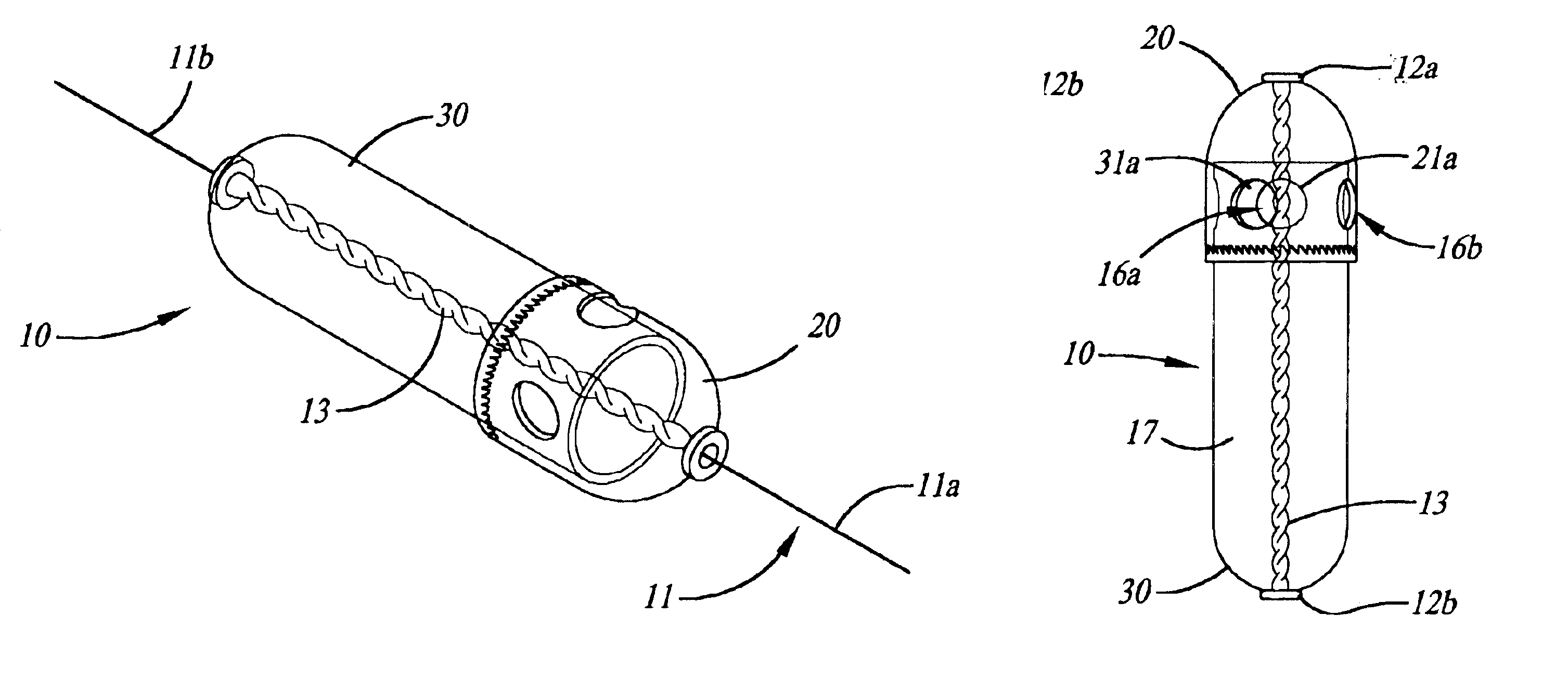
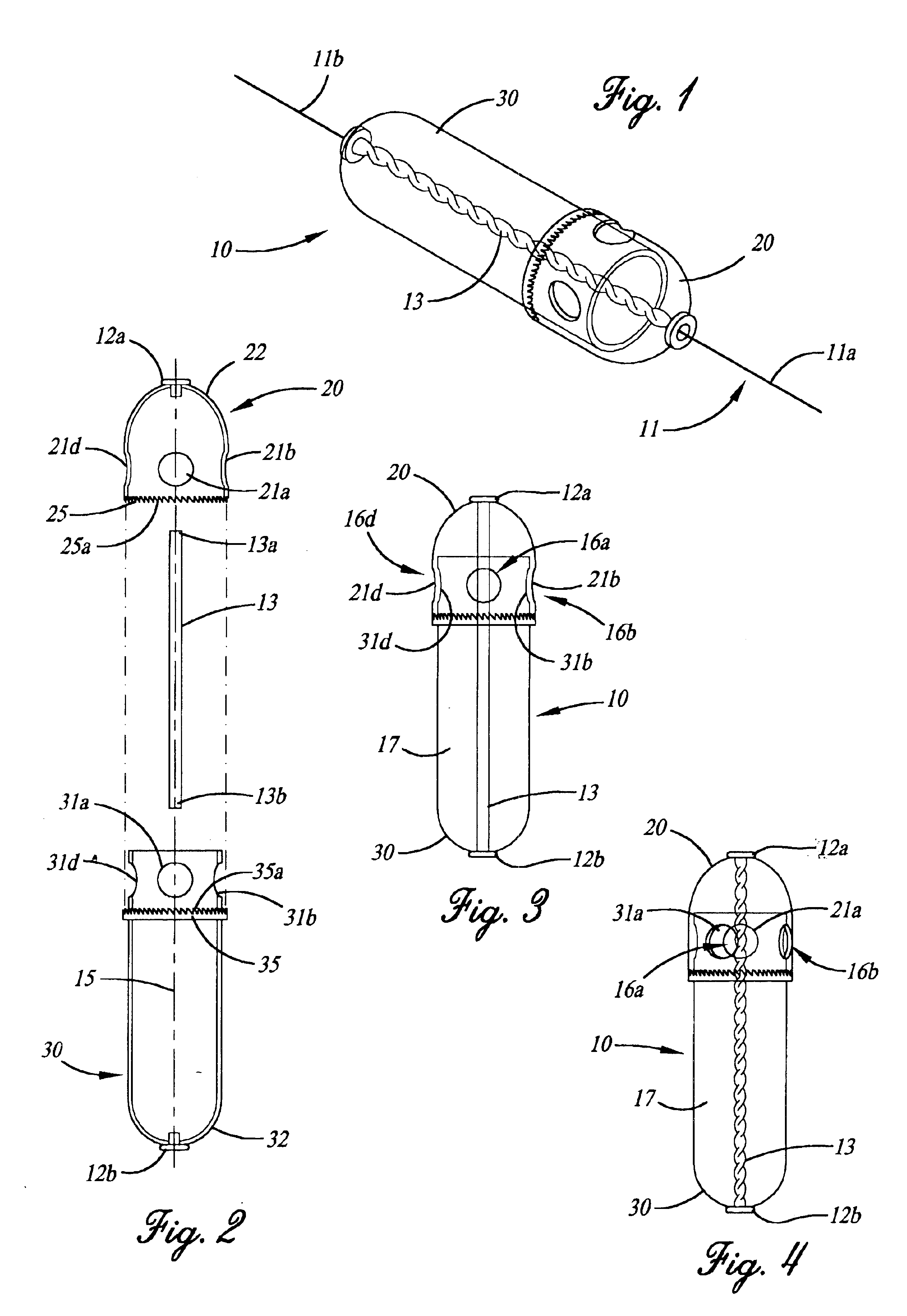
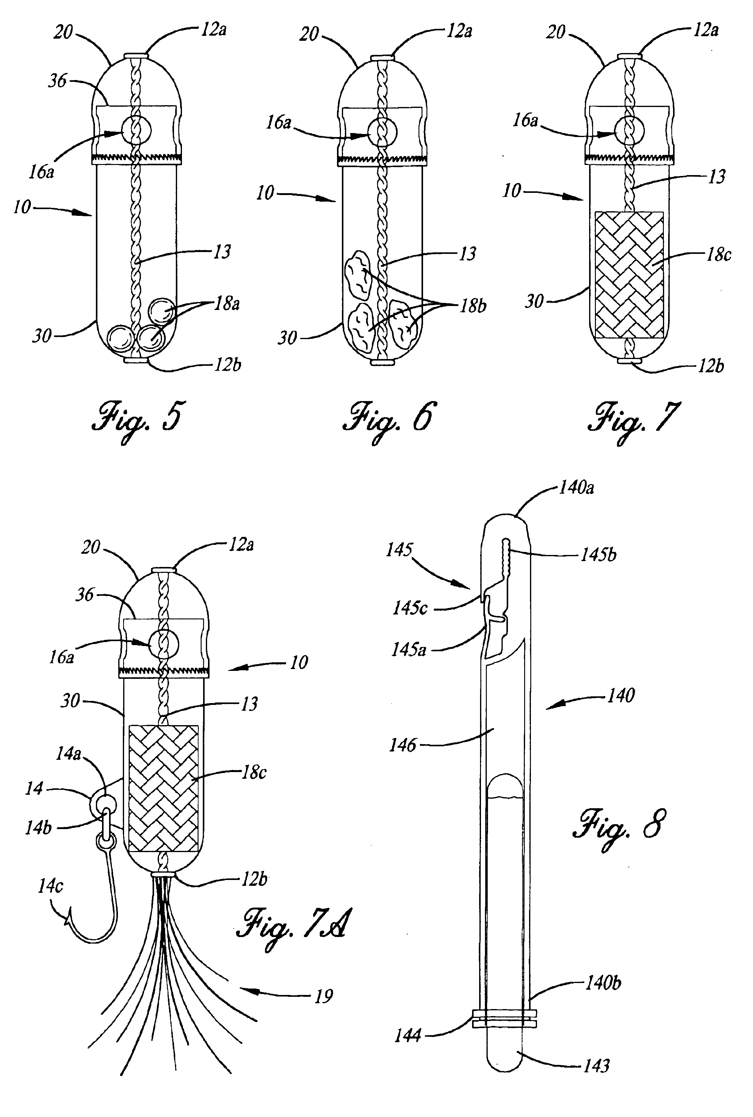
FIGS. 8-10 illustrate the adjustable buoyancy floating fish lure 100 of the present invention, wherein a hollow attaching rod 140 is centrally disposed through fore and aft chamber sections 120, 130 that is held in position by threaded end cap 150. The fore and aft chamber sections 120, 130, as well as the hollow attaching rod 140 and threaded end cap 150, are all preferably made of a transparent and colorless plastic which, due to the light weight of plastic and the absence of color, permits the fish lure of the present invention to display a covert natural appearance beneath the surface of the water.

As illustrated in FIG. 8, the hollow attaching rod 140 of the second embodiment of the present invention has first and second ends 140a and 140b, respectively. Strategically positioned at the first end 140a of the hollow attaching rod 140 is a line attachment means 145. Unlike the first embodiment of the present invention, fish lure 100 connects to the fishing line (not shown in FIGS. ...

first embodiment

Alternatively, to increase the buoyancy of the fishing lure 100 of the present invention, the size or area of the valve aperture openings 116a-d must be reduced as described above with respect to the present invention as depicted in FIG. 4. By reducing the size of the aperture valve openings, less water is accepted into the interior chamber 117, therefore allowing more air to remain within the interior chamber 117. For instance, in the situation where the buoyancy window 121a of the fore chamber section 120 only partially overlies the buoyancy window 131a of the aft chamber section 130, a relatively small valve aperture opening 116a is created when compared to the aperture valve opening 116a as depicted in FIGS. 9 and 9a. Although not shown in the drawings, to cause the fish lure of the present invention to act as a bobber and always float on top of the surface of the water, the fore and aft chamber sections 120, 130 are positioned relative to each other so that neither buoyancy win...


PUM


Abstract

A floating fishing lure having the capability to adjust the buoyancy of the fish lure with a high degree of precision, such that the fish lure has fore and aft chamber sections connected and held together by an attaching means. Disposed on each fore and aft chamber sections are a plurality of buoyancy windows, one set of which will coincidentally overlie the other set of buoyancy windows as the fore chamber section is rotationally moved in regard to the aft chamber section. By changing the rotational placement of the two sections, valve aperture openings are produced that regulate the air to water ratio within the fish lure, thereby controlling its buoyancy. Additional fish attractors, hooks and illuminators can be added to the fishing lure.

Description

FIELD OF THE INVENTIONThe present invention relates to an adjustable buoyancy floating fish lure having remote and manual buoyancy adjustments to vary the buoyancy of the fish lure, thereby controlling the water depth the fish lure will attain. The fish lure of the present invention comprises a fore and aft chamber held together by an attaching means and the buoyancy of the fish lure is adjusted by the relative rotation between the fore and aft chambers. The present invention is not limited to a fishing lure, but can also be used to control and maintain the depth of live bait and other lures.BACKGROUND OF THE INVENTIONFishing floatation devices have been used for centuries, utilizing cork objects and wood attached to fishing line to serve as bobbers. Such types of bobbers reside on the water surface and are desirable for preventing the hook from becoming caught or snared on the bottom of the body of water. Although conventional bobbers prevent the hooks from catching on rocks or tre...

Claims


Application Information

Patent Timeline
IPC IPC(8): A01K85/00A01K93/00
CPCA01K93/00A01K85/00
Inventor CRAMSEY, JOHN F.
Owner CRAMSEY JOHN F
Why Eureka
Try Eureka