Method and apparatus for determining respiratory system resistance during assisted ventilation

a technology of respiratory system and determination method, which is applied in the field of mechanical ventilation, can solve the problems of inability to estimate respiratory, inability to reliably, and clinically available, and achieve the effect of reducing the computational requirements necessary to determine respiratory and the time required

Inactive Publication Date: 2005-01-04
UNIVERSITY OF MANITOBA
View PDF14 Cites 132 Cited by
  • Summary
  • Abstract
  • Description
  • Claims
  • Application Information

AI Technical Summary

Benefits of technology

The method and apparatus described in detail herein in accordance with the present invention, represent a considerable simplification of the approach proposed by Younes in U.S. Pat. No. 5,884,622. As indicated above, the main obstacle to determining respiratory resistance during assisted ventilation is the uncertainty about what happens to Pmus during interventions in the course of the inflation phase of the ventilator. The comparison between perturbed and unperturbed breaths was the approach used in U.S. Pat. No. 5,884,622. By contrast, in accordance with the present invention, the behavior of Pmus during the intervention is predicted from estimates of the change in Pmus in the interval immediately preceding the intervention. In this manner, all the required information necessary to determine R can be obtained from a single intervention in a single breath. This approach greatly reduces the computational requirements necessary to determine R, and the time required to obtain information that is clinically useful, such as in assisted ventilation

Problems solved by technology

There are currently no reliable, clinically available, non-invasive means to estimate respiratory resistance (R) during inspiration in mechanically ventilated patients who have spontaneous respiratory efforts.
This component continuously changes during the inflation phase and cannot be estimated without prior knowledge of respiratory mechanics.
This requires knowledge of passive respiratory elastance (E) which is also difficult to determine in the presence of unquantifiable Pmus.
While this approach is capable of providing accurate information about R, it has several limitations.
Furthermore, for the same reasons, any true change in patient's resistance is not detected in a timely way.
Second, this approach requires at least two different kinds of perturbations.
Because, as indicated earlier, a large number of observations is required with each perturbation, this requirement delays the acquisition of reliable information further.
Third, the need to average large numbers of breaths and a large number of data points from each breath, greatly increases the computing and storage requirements of the computer used to process the information to provide the value of R. This requirement adds further strain on the extensive and highly complex operations carried out by modern, computer controlled ventilators.

Method used


Image

  • Method and apparatus for determining respiratory system resistance during assisted ventilation
  • Method and apparatus for determining respiratory system resistance during assisted ventilation
  • Method and apparatus for determining respiratory system resistance during assisted ventilation

Examples


Embodiment Construction

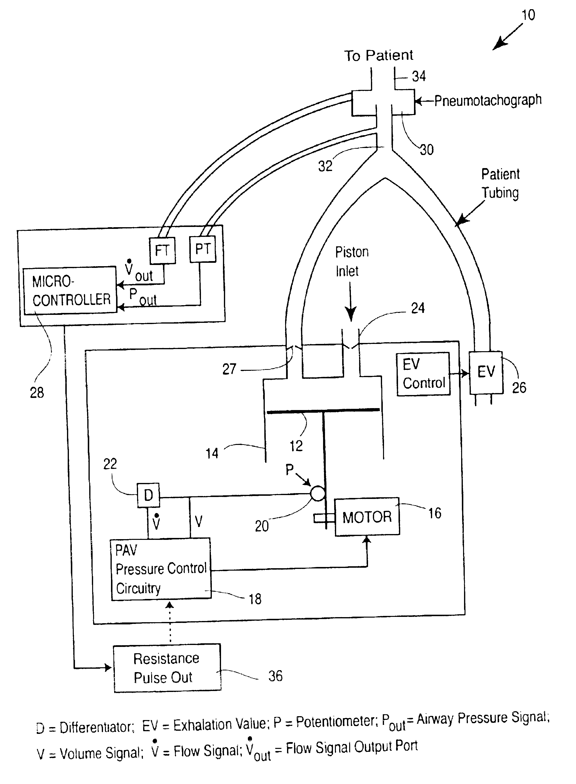
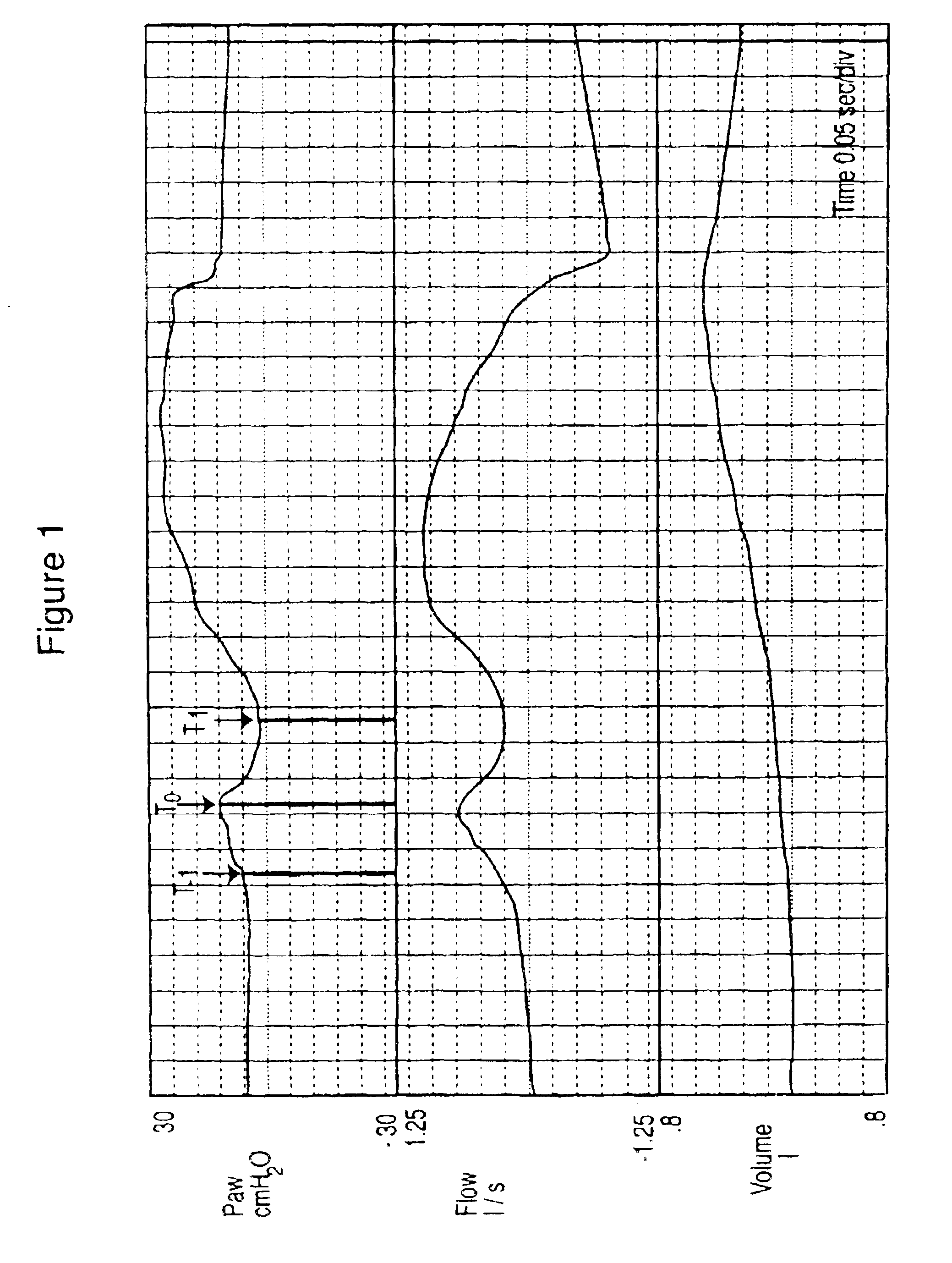
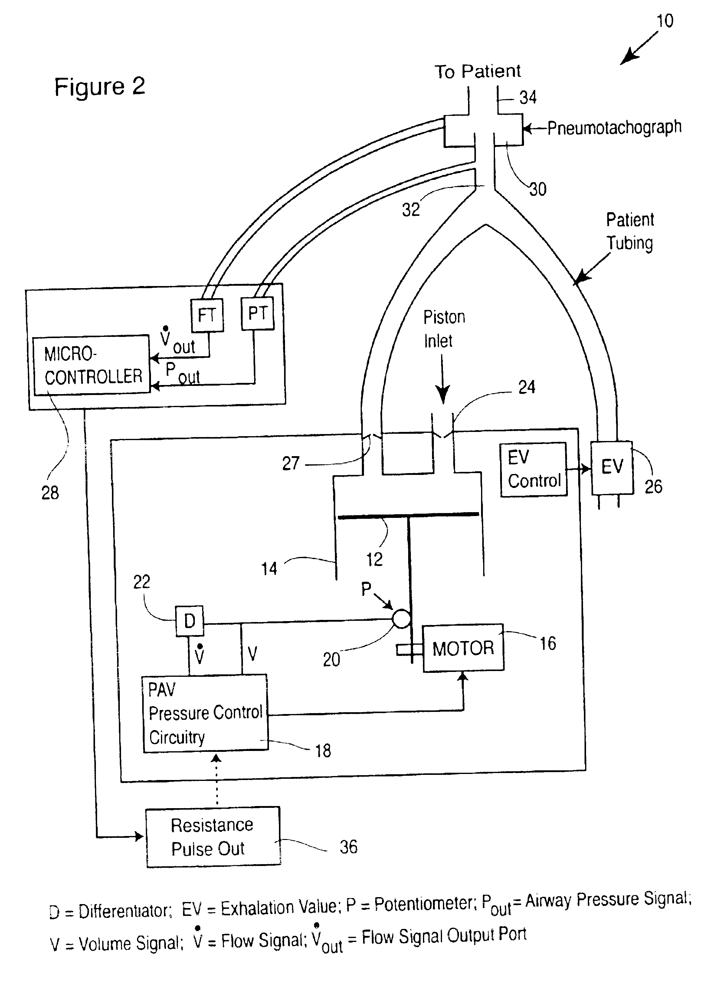
FIG. 2 shows an overview of a preferred embodiment of apparatus for carrying out the present invention. This preferred embodiment reflects the actual system used to validate the inventive procedures of the invention in 67 ventilator-dependent patients. The preferred embodiment has several components. Although in FIG. 2, these components are shown as distinct from each other, such representation is for the sake of illustration of these components, in actual practice all three components can be incorporated within a single unit (the ventilator).

A gas delivery unit 10 is a ventilator system that is capable of delivering proportional assist ventilation (PAV). A variety of mechanical systems can be used to deliver PAV and some are commercially available, which use blower-based, piston-based and proportional solenoid systems. PAV is described in U.S. Pat. No. 5,107,830 (Younes), assigned to the assignee hereof and the disclosure of which is incorprorated herein by reference. The ventilato...


PUM


Abstract

Method and apparatus are described for determining respiratory system resistance (R) in a patient receiving gas from a ventilator. A negative pulse in the pressure and / or flow output of the ventilator during selected inflation cycles is generated and Paw, {dot over (V)} and V are measured at a point (To) near the beginning of the pulse, at a point (T1) near the trough of the negative pulse and at a point (T−1) preceding To. The value of R is calculated from the difference between Paw, {dot over (V)} and V at To and at T1 and where the change in patient generated pressure (Pmus) in the interval To−T1 is estimated by extrapolation from the different between Paw, {dot over (V)} and V and To and at T−1, in accordance with Equation 8.

Description

FIELD OF INVENTIONThis invention relates to mechanical ventilation, and in particular, to assisted ventilation and the determination of respiratory system resistance.BACKGROUND TO THE INVENTIONThere are currently no reliable, clinically available, non-invasive means to estimate respiratory resistance (R) during inspiration in mechanically ventilated patients who have spontaneous respiratory efforts. Calculation of resistance requires knowledge of the force applied to the respiratory system which, in such patients, includes a component related to pressure generated by respiratory muscles (Pmus). This component continuously changes during the inflation phase and cannot be estimated without prior knowledge of respiratory mechanics. Furthermore, to isolate the component of total applied pressure that is dissipated against resistance (Pres), it is necessary to subtract the pressure used against the elastic recoil of the respiratory system. This requires knowledge of passive respiratory e...

Claims


Application Information

Patent Timeline
Patent Type & Authority Patents(United States)
IPC IPC(8): A61M16/00
CPCA61M16/00A61M2016/0036A61M2016/0021A61M16/0051A61M2016/0027A61M2230/46A61M16/0063A61M16/026
Inventor YOUNES, MAGDY
Owner UNIVERSITY OF MANITOBA
Why Eureka
Try Eureka