Apparatus for filling containers with viscous liquid food products

a technology of viscous liquid and apparatus, which is applied in the directions of liquid handling, packaging goods, transportation and packaging, etc., can solve the problems of not being able to adapt the apparatus, not being able to evacuate excess viscous liquid products, and exceeding the throughput rate of batch processing techniques

Inactive Publication Date: 2005-01-04
COTT TECH
View PDF5 Cites 1 Cited by
  • Summary
  • Abstract
  • Description
  • Claims
  • Application Information

AI Technical Summary

Benefits of technology

An object of the present invention is to provide an apparatus for rapidly filling quantities of containers with viscous and non-viscous liquid food products.

Problems solved by technology

Obviously, the through-put rate of this batch processing technique exceeds that of a container filling method in which individual containers are filled one at a time.
No means are disclosed to adapt the apparatus to handle viscous liquid food products, or how to make the apparatus meet C.I.P. requirements.
No means are disclosed for evacuating excess viscous liquid product from a container being filled.

Method used


Image

  • Apparatus for filling containers with viscous liquid food products
  • Apparatus for filling containers with viscous liquid food products
  • Apparatus for filling containers with viscous liquid food products

Examples


embodiment 30a

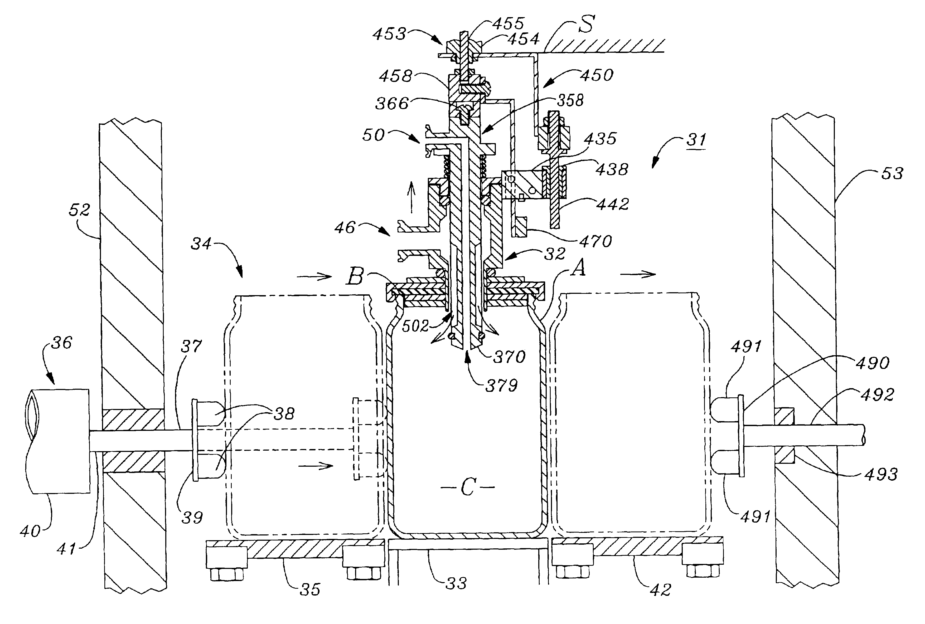
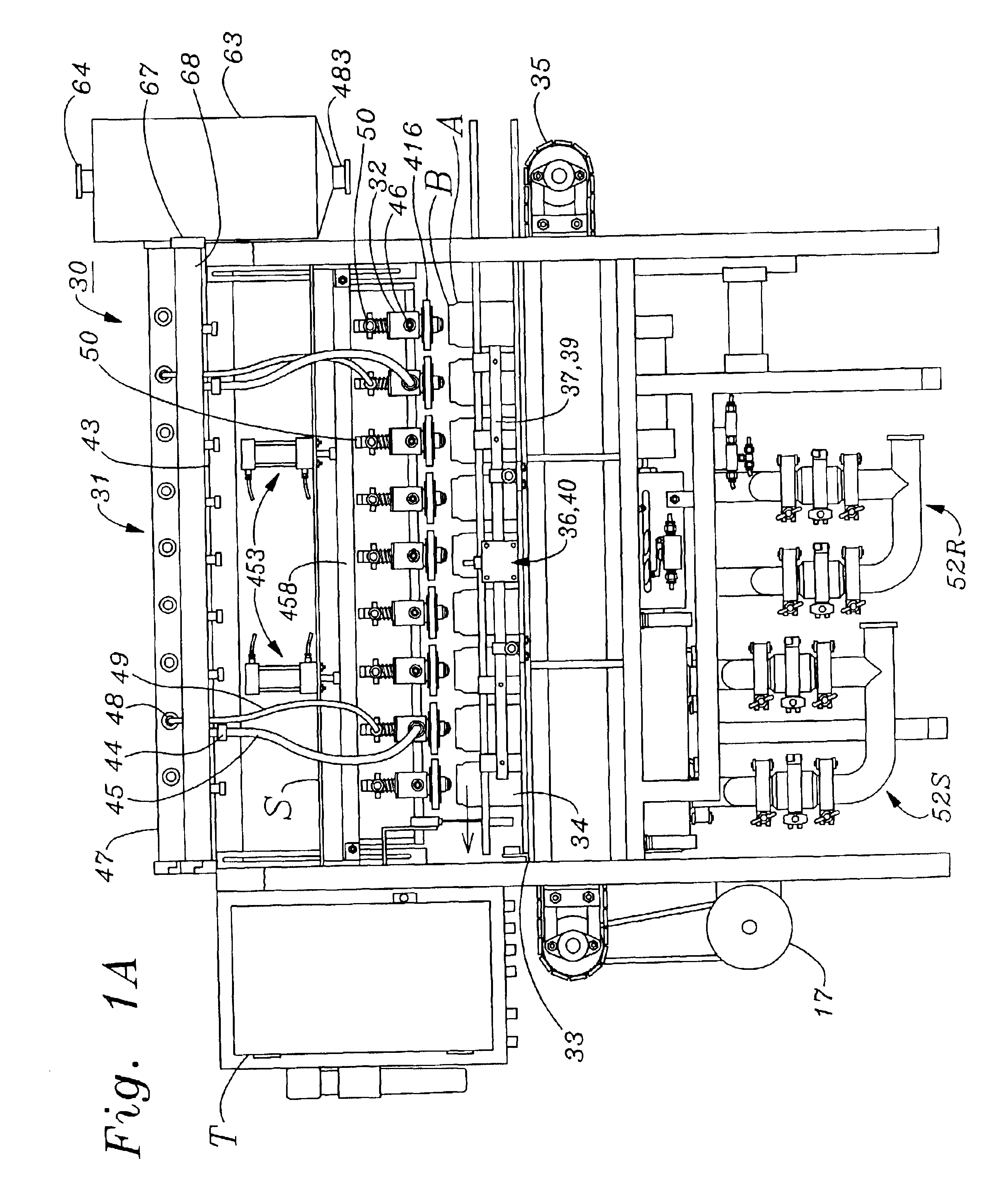
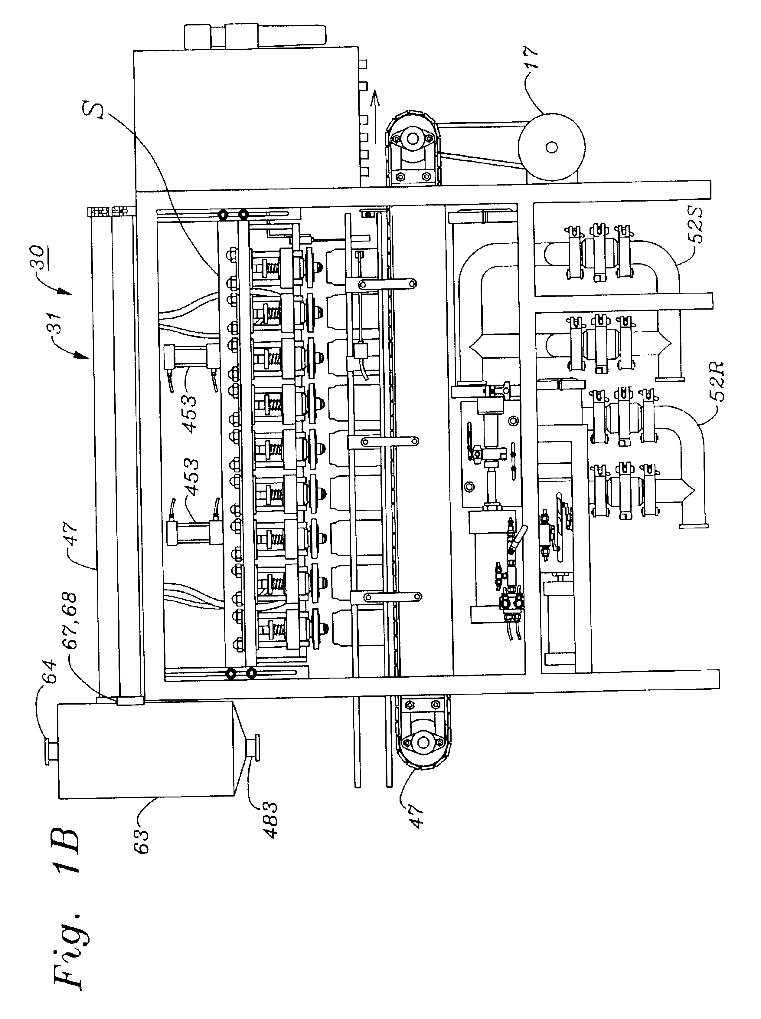
of apparatus 30 shown in FIG. 27A utilizes hydrostatic pressure of liquid food product contained in product supply tank 61 and product recovery tank 63 to supply liquid food product to inlet ports 46 of fill heads 32, thereby eliminating the requirement for a liquid product pump. This embodiment requires that the height hs of product supply tank 62, and hr of product recovery tank 63, both exceed the heights hf of inlet ports 46 of fill heads 32 by an amount equal to the hydrostatic pressure head required for a continuous flow of liquid product of a given viscosity to fill head input ports 46. As shown in FIG. 27A, liquid food product is supplied to product supply tank 61 through an inlet port 480. As is also shown in FIG. 27A, liquid food product flows through low pressure product supply hose 60 from outlet port 62 of product supply tank 61, and through a supply tank check valve 481 to a first inlet port of a Tee 482. Similarly, liquid food product flowing from an outlet port 483 o...


PUM

PropertyMeasurementUnit
viscositiesaaaaaaaaaa
pressureaaaaaaaaaa
forceaaaaaaaaaa

Abstract

An apparatus for filling containers with viscous food product includes a plurality of pressure/vacuum fill head positioned above a plurality of containers. Each fill head includes a housing enclosing a plenum through which is longitudinally disposed a valve stem having in an outer cylindrical surface thereof a plurality of longitudinally disposed grooves terminated near a lower end of the stem by a cylindrical boss. The boss is biased into fluid pressure-tight sealing contact with a lower transverse end face of lower tubular portion of the housing by a helical compression spring which fits coaxially over a portion of the valve stem which protrudes upwardly from the housing, the spring being disposed between an upper transverse end wall of the housing, and the lower surface of a neck which protrudes radially outwardly from the upper end of the valve stem. Attached coaxially over the lower end portion of the fill head housing is a resilient circular sealing pad assembly which is compressed into a liquid pressure-tight sealing contact with a container rim, when a horizontally disposed press bar exerts a downward pressure on a resilient bumper at the upper end of the valve stem. Further downward motion of the press bar after downward motion of the valve housing is halted by contact with a container rim causes the valve stem to be displaced downwards within the housing against the restraining force of the compression spring, thus causing the boss at the lower end of the valve stem to extend outwardly from the lower housing seat. This causes an annular opening to be formed around the lower ends of the valve stem grooves, thus enabling pressurized liquid food product supplied to the head by a product inlet import protruding radially outward from the housing to flow into the container. Excess liquid food product and air displaced from the container are removed through a vacuum port which is disposed coaxially through the stem, the vacuum port having a lower opening which penetrates the lower end face of the valve stem, and an upper opening in the outer end of the neck which is connected to a vacuum source.

Description

BACKGROUND OF THE INVENTIONA. Field of the InventionThe present invention relates to methods and apparatus used in manufacturing production lines for filling containers such as bottles and cans with liquid food products. More particularly, the invention relates to an apparatus for rapidly filling quantities of containers with a variety of liquid food products which have different viscosities, such as beverages and jellies.B. Description of Background ArtA wide variety of machines are used in product packaging lines for filling containers with liquid products. Ideally, such machines are capable of filling large quantities of containers with liquid products in a short time. In a typical installation of a machine for rapidly filling large quantities of containers with liquid products, empty containers are transported to the machine by an inlet conveyor, where a rotary or in-line arrangement of fill heads dispense liquid products simultaneously into individual containers. Obviously, the...

Claims


Application Information

Patent Timeline
Patent Type & Authority Patents(United States)
IPC IPC(8): B65B3/10B65B39/00B65B3/12
CPCB65B39/004B65B3/12
Inventor NAVARRO, RAMON
Owner COTT TECH
Why Eureka
Try Eureka